background image


.............................


CCEC/ OM Manuals RotaSec Titan 1.5   


08.2009


This Manual Refers to the RotaSec fitted with the Titan Head


 RotaSec 

– 

With Damping


Inst

all

ation O

per

ation and Mainte

nance Manual


Содержание RotaSec B120D

Страница 1: ...CCEC OM Manuals RotaSec Titan 1 5 08 2009 This Manual Refers to the RotaSec fitted with the Titan Head RotaSec With Damping Installation Operation and Maintenance Manual...

Страница 2: ...CCEC OM Manuals RotaSec Titan 1 5 08 2009...

Страница 3: ...ol Devices 16 Programmable Parameters 16 SECTION 4 TECHNICAL INFORMATION 17 Standard Features 17 Optional Features 17 Typical Layout Details 18 Typical Titan Head Mechanism Elevation 23 Drives and Con...

Страница 4: ...ciples of Setting To Work Fig 5 21 and 5 22 58 Variations for R Models 59 Variations for S Models 59 Electrical Connections 78 Testing after Installation 79 SECTION 6 MAINTENANCE 86 General Care 86 Ro...

Страница 5: ...ctrical units are to be undertaken only by persons fully aware of the danger involved and who have taken adequate precautions and training Errors Reports on errors comments and suggestions concerning...

Страница 6: ...nt facts and conditions Static Sensitive Devices Some of the PCBs within in the equipment which is covered by this technical manual contain Static Sensitive Devices It is recommended that maintenance...

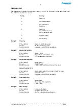
Страница 7: ...ting 2 General Installation Who is at Risk Site personnel Hazard Objects Tools in Installation area Current Controls Trained Installation Engineers Rating 4 General Maintenance Who is at Risk Site Per...

Страница 8: ...ry Low Voltage and EMC Directives With each unit a Declaration of Conformity is supplied Important Notice The Gunnebo RotaSec is a security product and as such any Children or Minors using the turnsti...

Страница 9: ...and cone bearing at the base On double units the rotors can be interlocked where space is of prime importance Entry and Exit can be made by Card reader Pushbutton or any other type of control device...

Страница 10: ...nels S120S Single Unit with canopy and side panels B90D Basic Double Unit open frame design without canopy B120D Basic Double Unit open frame design without canopy F90D Double Unit without canopy F120...

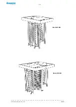
Страница 11: ...11 CCEC OM Manual RotaSec Titan 1 5 EN 08 2009 Typical Units Model B90S Model F90S...

Страница 12: ...12 CCEC OM Manual RotaSec Titan 1 5 EN 08 2009 Model R120S Model R120DI...

Страница 13: ...lock which prevents two passages at one time A self centring mechanism to ensure complete rotation of the head to the reset position A hydraulic damper to ensure smooth and quiet operation An anti bac...

Страница 14: ...ol logic with the following features Three inputs for sensor directing the mechanism position One input for opening locking the mechanism in each direction Two protected outputs for control of the ope...

Страница 15: ...the RotaSec in either direction 1 The Rotor will normally be locked unless a free entry exit option has been specified 2 Operate the Access Control Device if fitted 3 On the acceptance of a signal fro...

Страница 16: ...ble Parameters The system operation is conditioned by the values given to certain parameters stored in the LCM02 PCB When the control logic microprocessor executes the program it verifies the values o...

Страница 17: ...ard colours Walkway down lights not fitted on Basic Models Integral drain pipes only fitted to R and S Models Electro Mechanical head mechanism Rotor restoring mechanism Universal control logic Fail s...

Страница 18: ...eneral location of the main units assemblies that comprise the single RotaSec 90 Fig 4 1 Layout details RotaSec 90 Single Walkway Key to illustration A Rotor Head Mechanism B Electrical Plate Assembly...

Страница 19: ...neral location of the main units assemblies that comprise the single RotaSec 120 Fig 4 2 Layout details RotaSec 120 single walkway Key to illustration A Rotor Head Mechanism B Electrical Plate Assembl...

Страница 20: ...units assemblies that comprise the Double RotaSec 90 Fig 4 3 Layout details RotaSec 90 Double Walkway Key to illustration A Rotor Head Mechanism 1 B Rotor Head Mechanism 2 C Electrical Plate Assembly...

Страница 21: ...its assemblies that comprise the Double RotaSec 120 Fig 4 4 Layout details RotaSec 120 Double Walkway Key to illustration A Rotor Head Mechanism 1 B Rotor Head Mechanism 2 C Electrical Plate Assembly...

Страница 22: ...22 CCEC OM Manual RotaSec Titan 1 5 EN 08 2009 This section gives details of the main components that comprise a RotaSec Fig 4 5 90 O Titan Head Mechanism Fig 4 6 120 O Titan Head Mechanism...

Страница 23: ...1107 is available for this purpose Fine adjustment of the rotor home position in relation to the turnstile framework can be achieved by slackening the 4 x M12 mounting bolts in the slotted holes and r...

Страница 24: ...orce is always that required to rotate the unit to the next home position after the rotor has moved half way through the cycle following a release signal The length of the spring should be adjusted to...

Страница 25: ...is fairly critical and sensitive The restoring force can then be adjusted as in the previous section so that the rotor will return to the home position against the resistance of the damping Check this...

Страница 26: ...S1 output V01 for pass right anti clockwise rotation of the rotor When configured fail lock i e energise to release ideally the solenoids should be de energised to lock at the first sensor signal i e...

Страница 27: ...1 With solenoid de energised and plunger extended by action of the spring the locking pawl is held clear of the baffle plate outside diameter Adjust the position of solenoid coil if necessary with th...

Страница 28: ...ase clear of the baffle plate outside diameter De energise the solenoid and the pawl will re engage the ratchet block Electronic Circuit Boards Fig 4 12 Electrical Plate Assembly The mechanism has one...

Страница 29: ...OFF It displays the status of 14 inputs ON OFF OFF It allows the parameter programming SW2 It changes from parameter number parameter value Dot num parameter SW3 Decreases the displayed number SW4 Inc...

Страница 30: ...f two seven segment displays T1 and T2 and pushbuttons SW1 SW2 SW3 and SW4 Figure 4 13 Programming Pushbutton and Switch Locations Standard Jumper Settings JP 5 7 10 12 2 3 JP13 OFF JP14 OFF JP15 OFF...

Страница 31: ...tch between PARAMETER LOCATION and RELATIVE VALUE SW2 Location Value Pressing SW3 when a Location is displayed will move to a lower location SW3 Location Location Pressing SW3 when a Value is displaye...

Страница 32: ...TION IS DIFFERENT TO THOSE SET DURING FACTORY TESTING ANY CHANGES WILL DELETE THE ORIGINAL SETTINGS Parameter Default Setting The RotaSec always uses default 01 To select the default please follow thi...

Страница 33: ...is manual Sensor Board The board provides an interface between the Titan mechanism and the LCM02 Controller Logic Mounted on it are the position sensors for the rotary unit and all the connections req...

Страница 34: ...own on figure 5 27 29 Customer Connections section 5 Standard Jumper Settings JP1 On On On JP2 OFF JP3 NC JP4 NO JP5 Off On On JP6 NO JP7 NC JP8 Off M1 Alarms Y8 Pictograms A pin Description Pin Descr...

Страница 35: ...DL7 red On when aux alarm is activated DL8 yellow On when RL1 is activated It is fitted with two relays that provide ONE or ALL of the Alarms The Alarms are defined as follows Improper Transit Rotor P...

Страница 36: ...Loom Connections The solenoid connections can be configured on installation to match the head mechanisms configuration From Colour Pass Left Solenoid Common Black 24V F L Green 24V F S Orange Pass Ri...

Страница 37: ...ALLATION Site Preparation Ensure the site base area has been completed in accordance with the approved site installation drawing Reference to the Installation Figures Refer to Figs 5 1 to 5 20 should...

Страница 38: ...bility to ensure the structural integrity and strength of the installation location Bottom entry conduit location Stator bar dead area barrier Fixing locations Straight bar rotor Concrete of resistanc...

Страница 39: ...tomer s responsibility to ensure the structural integrity and strength of the installation location Bottom entry conduit location Stator bar dead area barrier Fixing locations Straight bar rotor Floor...

Страница 40: ...stomer s responsibility to ensure the structural integrity and strength of the installation location Bottom entry conduit location Stator bar dead area barrier Fixing locations Straight bar rotor Floo...

Страница 41: ...ure the structural integrity and strength of the installation location Bottom entry conduit location Stator bar dead area barrier Fixing locations Straight bar rotor Floor Anchors to be drilled during...

Страница 42: ...sure the structural integrity and strength of the installation location Bottom entry conduit location Stator bar dead area barrier Fixing locations Straight bar rotor Floor Anchors to be drilled durin...

Страница 43: ...structural integrity and strength of the installation location Bottom entry conduit location Stator bar dead area barrier Fixing locations Straight bar rotor Floor Anchors to be drilled during install...

Страница 44: ...structural integrity and strength of the installation location Bottom entry conduit location Fixing locations Straight bar rotor GRP canopy Walkway down light GRP side cabinet Stator bar dead area bar...

Страница 45: ...tomer s responsibility to ensure the structural integrity and strength of the installation location Stator bar dead area barrier Fixing locations Straight bar rotor Floor Anchors to be drilled during...

Страница 46: ...stomer s responsibility to ensure the structural integrity and strength of the installation location Floor Anchors to be drilled during installation 12mm dia x 100mm deep Concrete of resistance class...

Страница 47: ...stomer s responsibility to ensure the structural integrity and strength of the installation location Bottom entry conduit location Stator bar dead area barrier Fixing locations Straight bar rotor Floo...

Страница 48: ...is the customer s responsibility to ensure the structural integrity and strength of the installation location Concrete of resistance class at least fck cube 30 N mm2 Base to be flat and level to 5mm o...

Страница 49: ...ensure the structural integrity and strength of the installation location Fixing locations Floor Anchors to be drilled during installation 12mm dia x 100mm deep GRP canopy Walkway down lights Stator...

Страница 50: ...sponsibility to ensure the structural integrity and strength of the installation location Concrete of resistance class at least fck cube 30 N mm2 Base to be flat and level to 5mm over the SpeedStile f...

Страница 51: ...ensure the structural integrity and strength of the installation location Stator bar dead area barrier Straight bar rotor Floor Anchors to be drilled during installation 12mm dia x 100mm deep GRP can...

Страница 52: ...o ensure the structural integrity and strength of the installation location Concrete of resistance class at least fck cube 30 N mm2 Base to be flat and level to 5mm over the SpeedStile footprint area...

Страница 53: ...ep min per Unit IMPORTANT Any horizontal pipe or conduit runs below the RotaSec must be at least 140mm below FFL It is the customer s responsibility to ensure the structural integrity and strength of...

Страница 54: ...nsibility to ensure the structural integrity and strength of the installation location Concrete of resistance class at least fck cube 30 N mm2 Base to be flat and level to 5mm over the SpeedStile foot...

Страница 55: ...he structural integrity and strength of the installation location Fixing locations Straight bar rotor Floor Anchors to be drilled during installation 12mm dia x 100mm deep GRP canopy Walkway down ligh...

Страница 56: ...ensure the structural integrity and strength of the installation location Floor Anchors to be drilled during installation 12mm dia x 100mm deep Stator bar dead area barrier Concrete of resistance cla...

Страница 57: ...e conduit should be dedicated for the power supply from an external source and be run back to the nearest fused spur A triple core earthed 1 5mm 2 cable rated at a minimum of 10 amps should be provide...

Страница 58: ...ps 4 Assemble Items 6 and 7 ensuring that Item 6 is packed with grease and that the Bearing is Inserted in to the Bearing Cup 5 Fit and bolt together the items assembled in Step 1 and 2 using screws R...

Страница 59: ...etion of the Installation routines fit the Rain Water Down Pipe Cover by placing it in the hole provided in the GRP Roof Assembly Variations for S Models Omit Item No 2 of the Setting to Work Instruct...

Страница 60: ...60 CCEC OM Manual RotaSec Titan 1 5 EN 08 2009 Fig 5 22 Installation Model shown RotaSec F120S Fig 5 21 Installation Model shown RotaSec F90S...

Страница 61: ...61 CCEC OM Manual RotaSec Titan 1 5 EN 08 2009...

Страница 62: ...62 CCEC OM Manual RotaSec Titan 1 5 EN 08 2009 Fig 5 23 Frame Work installation details for the different Models Model B120S Basic Model F120S...

Страница 63: ...63 CCEC OM Manual RotaSec Titan 1 5 EN 08 2009 Model S90S Model R90S...

Страница 64: ...64 CCEC OM Manual RotaSec Titan 1 5 EN 08 2009 Model R120S Model S120S...

Страница 65: ...65 CCEC OM Manual RotaSec Titan 1 5 EN 08 2009 Model F90D...

Страница 66: ...66 CCEC OM Manual RotaSec Titan 1 5 EN 08 2009 Model F120D...

Страница 67: ...67 CCEC OM Manual RotaSec Titan 1 5 EN 08 2009 Model R90D...

Страница 68: ...68 CCEC OM Manual RotaSec Titan 1 5 EN 08 2009 Model R120D...

Страница 69: ...69 CCEC OM Manual RotaSec Titan 1 5 EN 08 2009 Model S90D...

Страница 70: ...70 CCEC OM Manual RotaSec Titan 1 5 EN 08 2009 Model S120D...

Страница 71: ...71 CCEC OM Manual RotaSec Titan 1 5 EN 08 2009 Model F90DI...

Страница 72: ...72 CCEC OM Manual RotaSec Titan 1 5 EN 08 2009 Model F120DI...

Страница 73: ...73 CCEC OM Manual RotaSec Titan 1 5 EN 08 2009 Model R90DI...

Страница 74: ...74 CCEC OM Manual RotaSec Titan 1 5 EN 08 2009 Model R120D...

Страница 75: ...75 CCEC OM Manual RotaSec Titan 1 5 EN 08 2009 Model S90DI...

Страница 76: ...76 CCEC OM Manual RotaSec Titan 1 5 EN 08 2009 Model S120DI...

Страница 77: ...77 CCEC OM Manual RotaSec Titan 1 5 EN 08 2009 Fig 5 24 Typical 90 O Rotor Assemblies Fig 5 25 Typical 120 O Rotor Assemblies...

Страница 78: ...Electrical Power Preparation Check the incoming mains supply is isolated Feed the mains supply cable through the RotaSec towards the MCB Cut back and strip the sleeving as shown in Fig 5 26 Remove th...

Страница 79: ...the following checks and tests be carried out Power Switch ON the mains power and the mains circuit breaker unit Mechanism Rotate the Rotor and check for parking position restoring and damping for a m...

Страница 80: ...entary signal Battery Back Up 24vDC Option From Power Supply Unit 24vDC Auxiliary DC Supply Locking Solenoids To Sensor PCB Traffic Status Lights 500mA typical 1A max Card Reader Reset 0v Card Reader...

Страница 81: ...nterface Connections Count signal Service Counter signal Audible Alarm 24vDC 40mA max 24v Supply Power Fail output 0v Emergency Fire Alarm 0v NC System Reset 0v momentary signal From LCM02 JP9 Passage...

Страница 82: ...82 CCEC OM Manual RotaSec Titan 1 5 EN 08 2009 Mains Power Supply 115 230vAC 50 60Hz Fig 5 29 Interface Connection Schematic Sensor PCB Controller PCB To Downlights Interface Connection PCB...

Страница 83: ...M Manual RotaSec Titan 1 5 EN 08 2009 Optional Equipment Figure 5 30 and 5 31 give details of how to install optional items i e Status Lights and Pushbuttons for the F and R model ranges Fig 5 30 Stat...

Страница 84: ...84 CCEC OM Manual RotaSec Titan 1 5 EN 08 2009 Fig 5 31 Optional Pushbuttons...

Страница 85: ...a single steel ball running in a housing Remember to insert the ball when the rotor column is fitted The bearing MUST be charged with the special grease supplied General Assembly Notes When all wiring...

Страница 86: ...ith soap and water rinse well with clean water and wipe dry Rust and other Corrosion products Stainless Finishes Cleaning agent Oxalic acid The cleaning solution should be applied with a swab and allo...

Страница 87: ...d before inspecting the mechanism Servicing Access All serviceable components can be accessed by the removal of all service hatches or from above the enclosure by removing the roof cover Ensure the se...

Страница 88: ...efitted Disconnect the power supplies Remove all connectors from the PCB If necessary remove the PCB supports and the small chip in Master side LCM02 Disconnect the flat cable from the UCM95 if the PC...

Страница 89: ...r cam of the rotary unit When the rotor is in the barrier position segment b should be illuminated Segments d and g also flash but these reproduce the signals generated by the internal logic of the LC...

Страница 90: ...eck all electrical wiring for security of connectors Check supply fuses are serviceable Check Mains input supply is correct Check fuses on LCM02 Card reader entrance device faulty Check 24v is present...

Страница 91: ...arts Code Description Qty SE LA MU 0007 Bulb 35W Clear 12V 2 SE FU MU 0013 Fuse Mains 24mm 3A 2 SE SO MU 0013 Locking Solenoid 1 SA DA MU 0003 Damper if fitted 1 SM SH MU 0037 Tension Pin M4 x 25 1 SM...

Страница 92: ...29 1D 00011101 93 5D 01011101 157 9D 10011101 221 DD 11011101 30 1E 00011110 94 5E 01011110 158 9E 10011110 222 DE 11011110 31 1F 00011111 95 5F 01011111 159 9F 10011111 223 DF 11011111 32 20 00100000...

Страница 93: ...e not engaged OE OF OF OF Riservato Reserved do not modify OF 14 14 14 PTOFineRot 1 100sec Magnet block time after a normal passage in unlock e single passage mode 10 14 14 14 PTODisinverso 1 10sec Op...

Страница 94: ...s Waiting dir A 0 Green 1 Red TABLE 4 PSetLettori Bit 7 Bit 6 Bit 5 Bit 4 Bit 3 Bit 2 Bit 1 0 Accumulated credits 0 Not ordered 1 Order in a table 1 Reader resets alarms Only if PMaxPrenotaz 0 Number...

Страница 95: ...block time after a normal passage in unlock e single passage mode 10 14 14 14 PTODisInverso 1 10 sec Opposite direction blocking time 11 64 64 64 PTOPosiz 1 10 sec Position sensing timeout for arm ou...

Страница 96: ...Waiting dir A 0 Green 1 Red TABLE 4 PSetLettori Bit 7 Bit 6 Bit 5 Bit 4 Bit 3 Bit 2 Bit 1 0 Accumulated credits 0 Not ordered 1 Order in a table 1 Reader resets alarms Only if PMaxPrenotaz 0 Number of...

Страница 97: ...97 CCEC OM Manuals RotaSec Titan 1 5 08 2009 Section 9 Declaration of Conformity Declaration of Conformity...

Страница 98: ...98 CCEC Product Data CCEC O M Manuals ClearSec 1 3 09 2008 Notes...

Страница 99: ...99 CCEC OM Manual RotaSec Titan 1 5 EN 08 2009 Notes...

Страница 100: ...K Tel 44 0 1825 761022 Fax 44 0 1825 763835 E mail info entrancecontrol gunnebo com Web www gunnebo com A COMPANY WITHIN THE GUNNEBO GROUP HEAD OFFICE SWEDEN Gunnebo AB Box 5181 SE 402 26 Goteborg SWE...

Отзывы: