actuator drops below 60 psi, bypass valves within the actuator open to
allow the actuator piston to idle. With the actuator piston idling, the system
is said to be in manual reversion, technically explained in the following
paragraph.
The actuator input crank and output crank rotate on a common pivot point.
They are linked by a pin and elongated slot arrangement. The input crank
is on the pin and the output crank is on the slot. With the actuator piston
idling, the pin moves within the slot until it reaches either end. At this point,
mechanical contact is made and the input crank now drives the output
crank. The output crank in turn drives the left and right elevators through its
push-pull rods and cranks.
Manual reversion of the pitch flight control system is also possible by
closing a normally open flight power shutoff valve. The flight power shutoff
valve is a mechanically operated shutoff valve located between the
Combined and Flight hydraulic system pressure sources and the elevator
actuator (as well as the aileron, rudder and flight / ground spoiler actuator)
pressure lines. The valve consists of two mechanically connected but
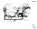
hydraulically isolated sections. A controlex cable connects the valve to a
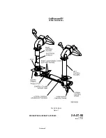
FLIGHT POWER SHUT OFF handle located on the left aft side of the
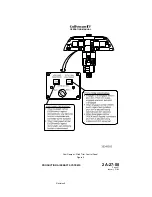
cockpit center pedestal. See Figure 8.
Moving the FLIGHT POWER SHUT OFF handle up from its stowed
(horizontal) position to the vertical position mechanically closes the flight
power shutoff valve. With the valve closed, operating pressure is removed
from the actuator, allowing the piston to idle.
The resultant advantage of the flight power shutoff provision is the ability to
bypass a malfunctioning actuator (such as would be the need in the
unlikely event of an actuator jam) and manually fly the aircraft. Although
control column effort and response time to inputs are increased while in
manual reversion, the aircraft remains capable of positive and harmonious
control.
E. Pitch Trim System:
(See Figure 5 and Figure 9.)
(1) Elevator Trim Tabs:
A trim tab is installed on the trailing edge of each elevator. The tabs
are mechanically positioned through cable-driven drum actuators
located in each elevator. The trim actuators can be operated
manually or electrically as described in the following paragraphs.
Elevator trim tab travel ranges from 22
±
1° tab trailing edge down
(aircraft nose up) to 8
±
1° tab trailing edge up (aircraft nose down).
(2) Manual Trim Control:
Manual control of pitch trim is accomplished by an interconnected
manual trim control wheel set. A trim control wheel and elevator trim
scale are provided on each side of the cockpit center pedestal. With
electric pitch trim disengaged, moving either manual trim control
wheel adjusts pitch trim to the desired setting; the opposite wheel
moves in unison. With electric pitch trim engaged, both manual trim
control wheels move in unison corresponding to the amount of
electric pitch trim movement. Each elevator trim scale range is
incremented to a maximum of 22 units aircraft nose-up (22
±
1° tab
OPERATING MANUAL
PRODUCTION AIRCRAFT SYSTEMS
2A-27-00
Page 9
January 31/02
Revision 6
Содержание IV
Страница 3: ...GIV Flight Controls Aerodynamic Axes Figure 1 OPERATING MANUAL 2A 27 00 Page 3 4 January 31 02 ...
Страница 4: ...GIV Flight Controls Fluid Power Diagram Figure 2 OPERATING MANUAL 2A 27 00 Page 5 6 January 31 02 ...
Страница 16: ...Stall Barrier Angle of Attack Wiring Schematic Figure 4 OPERATING MANUAL 2A 27 00 Page 19 20 January 31 02 ...
Страница 17: ...Pitch Trim Controls Figure 5 OPERATING MANUAL 2A 27 00 Page 21 22 January 31 02 ...
Страница 32: ...Rudder Pedals Forward Linkage Figure 13 OPERATING MANUAL 2A 27 00 Page 39 40 January 31 02 ...
Страница 50: ...Flaps Simplified Block Diagram Figure 18 OPERATING MANUAL 2A 27 00 Page 61 62 January 31 02 ...
Страница 51: ...Flaps Simplified Electrical Diagram Figure 19 OPERATING MANUAL 2A 27 00 Page 63 64 January 31 02 ...
Страница 65: ...Spoiler Speed Brake Controls and Indications Figure 23 OPERATING MANUAL 2A 27 00 Page 79 80 January 31 02 ...
Страница 66: ...Ground Spoiler Controls and Indications Figure 24 OPERATING MANUAL 2A 27 00 Page 81 82 January 31 02 ...


