extended is prohibited.
The resultant advantage of the flight power shutoff provision is the ability to
bypass a malfunctioning actuator (such as would be the need in the
unlikely event of an actuator jam) and manually fly the aircraft. Although
control column effort and response time to inputs are increased while in
manual reversion, the aircraft remains capable of positive and harmonious
control.
3. Controls and Indications:
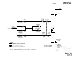
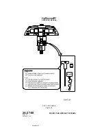
(See Figure 23 and Figure 24.)
A. Circuit Breakers (CBs):
Circuit Breaker Name:
CB Panel:
Location:
Power Source:
GND SPOILER
CPO
C-6
Left Main DC Bus
SPD BRAKE/FLAP ALARM
P
D-4
Essential DC Bus
B. Warning (Red) Messages and Annunciations:
CAS Message:
SWLP Indication
Cause or Meaning:
ACFT
CONFIGURATION
ACFT CONFIG
Position of one or more of the
following controls is not correct:
•
FLAP Handle
•
SPEED BRAKE Handle
•
Landing Gear Control Handle
GND SPOILER
GND SPOILER
Failure of ground spoiler
component or deployed ground
spoiler panel.
Annunciation:
Cause or Meaning:
Red NO GND SPOILERS light on
windshield center post.
Failure of ground spoiler component or
deployed ground spoiler panel.
C. Advisory (Blue) Messages and Annunciations:
CAS Message:
Cause or Meaning:
GND SPOILER
UNARM
Ground spoiler system is not armed.
SPD BRAKE
EXTNDED
Speed brakes are extended.
SPD BRAKE SWITCH
FWC and FGC disagree on position of speed brakes.
Annunciation:
Cause or Meaning:
SPEED BRAKE handle illuminated (pale
blue).
SPEED BRAKE handle not in RETRACT
detent.
4. Limitations:
A. Flight Manual Limitations:
(1) Use of Speed Brakes:
Speed brakes are not approved for extension with flaps at 39°
(DOWN) or with landing gear extended in flight.
(2) Use of FLIGHT POWER SHUTOFF:
Do NOT pull FLIGHT POWER SHUTOFF handle with speed brakes
extended.
OPERATING MANUAL
PRODUCTION AIRCRAFT SYSTEMS
2A-27-00
Page 74
January 31/02
Revision 6
Содержание IV
Страница 3: ...GIV Flight Controls Aerodynamic Axes Figure 1 OPERATING MANUAL 2A 27 00 Page 3 4 January 31 02 ...
Страница 4: ...GIV Flight Controls Fluid Power Diagram Figure 2 OPERATING MANUAL 2A 27 00 Page 5 6 January 31 02 ...
Страница 16: ...Stall Barrier Angle of Attack Wiring Schematic Figure 4 OPERATING MANUAL 2A 27 00 Page 19 20 January 31 02 ...
Страница 17: ...Pitch Trim Controls Figure 5 OPERATING MANUAL 2A 27 00 Page 21 22 January 31 02 ...
Страница 32: ...Rudder Pedals Forward Linkage Figure 13 OPERATING MANUAL 2A 27 00 Page 39 40 January 31 02 ...
Страница 50: ...Flaps Simplified Block Diagram Figure 18 OPERATING MANUAL 2A 27 00 Page 61 62 January 31 02 ...
Страница 51: ...Flaps Simplified Electrical Diagram Figure 19 OPERATING MANUAL 2A 27 00 Page 63 64 January 31 02 ...
Страница 65: ...Spoiler Speed Brake Controls and Indications Figure 23 OPERATING MANUAL 2A 27 00 Page 79 80 January 31 02 ...
Страница 66: ...Ground Spoiler Controls and Indications Figure 24 OPERATING MANUAL 2A 27 00 Page 81 82 January 31 02 ...

