FLIGHT CONTROLS
2A-27-10: General
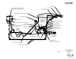
The Gulfstream IV primary flight controls system, shown in Figure 1, is a mechanically
actuated, hydraulically operated system that provides boosted surface control to
overcome the aerodynamic forces associated with high speed flight. This allows the
aircraft to be comfortably and reliably steered through the pitch, roll and yaw axes.
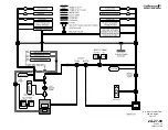
The primary flight control surfaces (elevators, ailerons and rudder) are positioned by
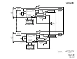
tandem type hydraulic actuators. The actuators receive hydraulic operating pressure
from both the Combined and Flight hydraulic systems, as shown in Figure 2. Both
hydraulic systems maintain a system pressure of 3000 psi. Loss of a single hydraulic
system has no effect on operation of the primary flight controls, as the remaining system
is capable of maintaining actuator load capacity. In the event of total loss of hydraulic
pressure in both hydraulic systems, the primary flight controls revert to manual operation.
Mechanical pitch, roll and yaw trim systems allow the flight crew to trim the aircraft. The
pitch trim system can also be controlled electrically by pitch trim switches on the control
wheels.
A gust lock secures the elevators, ailerons and rudder to prevent wind gust damage to
the surfaces.
Secondary flight controls, shown in Figure 1, include flaps, ground spoilers and
speedbrakes. These flight controls are hydraulically powered and electrically or
mechanically controlled. The mechanically operated horizontal stabilizer moves in
conjunction with the flaps to maintain longitudinal trim.
An Angle-of-Attack (AOA) system provides outputs to the control column shakers, control
column pusher, approach indexers, normalized AOA display and stall barrier system. The
control column shakers provides early warning of a stall scenario by vibrating the control
column before the stall while the control column pusher automatically initiates lowering
the nose if the stall is imminent.
The Gulfstream IV uses an aircraft configuration warning system to monitor landing gear,
flap, speed brake and power lever position. If an unsafe configuration is detected, the
system provides a visual and / or aural warning.
On CAA certified aircraft, a flight control automatic failure detection system compares
control inputs to actuator outputs. If a malfunction is detected, the system shuts off power
to the affected actuator.
The flight controls system is divided into the following subsystems:
•
2A-27-20: Pitch Flight Control System
•
2A-27-30: Yaw Flight Control System
•
2A-27-40: Roll Flight Control System
•
2A-27-50: Horizontal Stabilizer System
•
2A-27-60: Flaps System
•
2A-27-70: Spoiler System
•
2A-27-80: Gust Lock System
OPERATING MANUAL
PRODUCTION AIRCRAFT SYSTEMS
2A-27-00
Page 1
January 31/02
Revision 6
Содержание IV
Страница 3: ...GIV Flight Controls Aerodynamic Axes Figure 1 OPERATING MANUAL 2A 27 00 Page 3 4 January 31 02 ...
Страница 4: ...GIV Flight Controls Fluid Power Diagram Figure 2 OPERATING MANUAL 2A 27 00 Page 5 6 January 31 02 ...
Страница 16: ...Stall Barrier Angle of Attack Wiring Schematic Figure 4 OPERATING MANUAL 2A 27 00 Page 19 20 January 31 02 ...
Страница 17: ...Pitch Trim Controls Figure 5 OPERATING MANUAL 2A 27 00 Page 21 22 January 31 02 ...
Страница 32: ...Rudder Pedals Forward Linkage Figure 13 OPERATING MANUAL 2A 27 00 Page 39 40 January 31 02 ...
Страница 50: ...Flaps Simplified Block Diagram Figure 18 OPERATING MANUAL 2A 27 00 Page 61 62 January 31 02 ...
Страница 51: ...Flaps Simplified Electrical Diagram Figure 19 OPERATING MANUAL 2A 27 00 Page 63 64 January 31 02 ...
Страница 65: ...Spoiler Speed Brake Controls and Indications Figure 23 OPERATING MANUAL 2A 27 00 Page 79 80 January 31 02 ...
Страница 66: ...Ground Spoiler Controls and Indications Figure 24 OPERATING MANUAL 2A 27 00 Page 81 82 January 31 02 ...


