de-energizes to close the flap shutoff valve, a signal is sent causing an
amber FLAP ASYMMETRY caution message is displayed on the Crew
Alerting System (CAS).
For SPZ-8000 equipped aircraft having ASC 69A incorporated: When
the flap control relay de-energizes to close the flap shutoff valve, a signal is
sent causing an amber FLAP ASYM indicator (below the FLAP / STAB
position indicator) to illuminate.
H. Flap Position Indication System:
A flap position transmitter is installed on the central gearbox. As the flaps
extend and retract, an output shaft on the gearbox rotates the transmitter
shaft, sending an electrical signal to the FLAP pointer on the FLAP / STAB
position indicator.
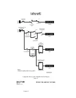
I. Aircraft Configuration Warning System:
(See Figure 21.)
An aircraft configuration warning system monitors speed brake, power
lever and flap position to provide visual and aural warnings of an unsafe
aircraft configuration both on the ground and in flight.
The system receives inputs from the landing gear handle, speed brake
handle, power lever takeoff power, flap follow-up switches and nutcracker
switches. The Fault Warning Computers (FWCs) receive these inputs and
generate the appropriate warnings if an unsafe configuration is detected.
A red ACFT CONFIGURATION warning message will be displayed on
CAS, along with the associated warning tone, whenever the following
conditions exist:
•
Extending the flaps to DOWN (39°) in flight with the SPEED BRAKE
handle not in the RETRACT detent
•
Extending the landing gear in flight with the SPEED BRAKE handle
not in the RETRACT detent
•
Advancing either power lever above 80% HP RPM on the ground
with the SPEED BRAKE handle not in the RETRACT detent
•
Advancing either power lever above 80% HP RPM on the ground
with the FLAP handle set to UP (0°) or DOWN (39°), i.e., flaps not in
the takeoff range of 10° or T/O APPR (22°)
For aircraft having a Standby Warning Lights Panel (SWLP) installed, a red
ACFT CONFIG light will be illuminated whenever the following conditions
exist:
•
Extending the flaps past T/O APPR (22°) in flight with the SPEED
BRAKE handle not in the RETRACT detent
•
Extending the landing gear in flight with the SPEED BRAKE handle
not in the RETRACT detent
•
Advancing either power lever above the takeoff power range on the
ground with the SPEED BRAKE handle not in the RETRACT detent
•
Advancing either power lever above the takeoff power range on the
ground with the FLAP handle set to UP (0°) or DOWN (39°), i.e.,
flaps not in the takeoff range of 10° or T/O APPR (22°)
OPERATING MANUAL
PRODUCTION AIRCRAFT SYSTEMS
2A-27-00
Page 58
January 31/02
Revision 6
Содержание IV
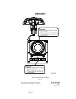
Страница 3: ...GIV Flight Controls Aerodynamic Axes Figure 1 OPERATING MANUAL 2A 27 00 Page 3 4 January 31 02 ...
Страница 4: ...GIV Flight Controls Fluid Power Diagram Figure 2 OPERATING MANUAL 2A 27 00 Page 5 6 January 31 02 ...
Страница 16: ...Stall Barrier Angle of Attack Wiring Schematic Figure 4 OPERATING MANUAL 2A 27 00 Page 19 20 January 31 02 ...
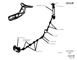
Страница 17: ...Pitch Trim Controls Figure 5 OPERATING MANUAL 2A 27 00 Page 21 22 January 31 02 ...
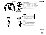
Страница 32: ...Rudder Pedals Forward Linkage Figure 13 OPERATING MANUAL 2A 27 00 Page 39 40 January 31 02 ...
Страница 50: ...Flaps Simplified Block Diagram Figure 18 OPERATING MANUAL 2A 27 00 Page 61 62 January 31 02 ...
Страница 51: ...Flaps Simplified Electrical Diagram Figure 19 OPERATING MANUAL 2A 27 00 Page 63 64 January 31 02 ...
Страница 65: ...Spoiler Speed Brake Controls and Indications Figure 23 OPERATING MANUAL 2A 27 00 Page 79 80 January 31 02 ...
Страница 66: ...Ground Spoiler Controls and Indications Figure 24 OPERATING MANUAL 2A 27 00 Page 81 82 January 31 02 ...

