


•
Autopilot / stall barrier disconnect (A/P DISC / BARR DISC)
•
Radio / intercom push-to-talk (RADIO / ICS)
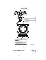
A torque shaft in the top of the control column transmits left and right
control wheel movement through a universal joint to a vertical torque tube
that descends through the column. The torque tube, in turn, connects to a
two-armed crank at the base of the column. On the rear facing arm of the
crank, a pushrod assembly interconnects the pilot’s and copilot’s control
wheels. The aileron control cables are connected to the outboard facing
arm of the crank. Non-adjustable stops in the control column limit control
wheel movement to 90° left or right of neutral.
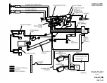
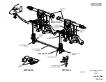
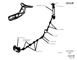
B. Mechanical Actuation System:
(See Figure 15.)
Control wheel inputs are transmitted rearward through a synchronized
system of pushrods, bellcranks, cables and sector assemblies. The system
transmits the inputs to the outboard sector assembly. The outboard sector
assembly operates the pushrods and bellcranks that form the input and
output cranks. Cradled between these cranks is the aileron actuator. The
leverage ratio of the input and output cranks provides a 5:1 boost ratio, i.e.,
one unit of work supplied by the flight crew through the control wheel
results in five units of work provided by the actuator. Movement of the input
and output cranks about a common pivot point displaces the aileron
actuator servo control valve input lever.
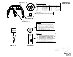
C. Hydraulic Boost System:
The aileron actuator is a dual tandem actuator consisting of two pistons
secured to a common shaft. The pistons move inside a common cylinder
divided to create two separate cylinders. One cylinder receives Flight
hydraulic system pressure while the other cylinder receives Combined
hydraulic system pressure.
Mechanical movement of the actuator input lever moves the servo control
valve from its neutral position. The servo control valve then directs
hydraulic pressure to one of the actuator’s two cylinders and connects
each cylinder’s opposite side to return. When the aileron reaches the
desired deflection, the servo control valve shifts to its neutral position to
lock hydraulic pressure within the actuator, in effect preventing further
surface movement.
D. Manual Reversion System:
During normal flight operations, the Combined and Flight hydraulic
systems each supply and maintain 3000 psi to the aileron actuators. Loss
of system pressure due to a single system failure has no effect on
operation of the roll flight control system.
Loss of system pressure from both hydraulic systems will automatically
revert the roll flight control system to manual control. As pressure at each
actuator drops below 60 psi, bypass valves within the actuator open to
allow the actuator piston to idle. With the actuator piston idling, the system
is said to be in manual reversion. The ailerons are now controlled solely by
mechanical means; the flight spoilers are inoperative.
Manual reversion of the roll flight control system is also possible by closing
a normally open flight power shutoff valve. The flight power shutoff valve is
OPERATING MANUAL
PRODUCTION AIRCRAFT SYSTEMS
2A-27-00
Page 43
January 31/02
Revision 6
Содержание IV
Страница 3: ...GIV Flight Controls Aerodynamic Axes Figure 1 OPERATING MANUAL 2A 27 00 Page 3 4 January 31 02 ...
Страница 4: ...GIV Flight Controls Fluid Power Diagram Figure 2 OPERATING MANUAL 2A 27 00 Page 5 6 January 31 02 ...
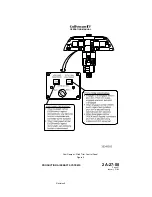
Страница 16: ...Stall Barrier Angle of Attack Wiring Schematic Figure 4 OPERATING MANUAL 2A 27 00 Page 19 20 January 31 02 ...
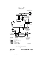
Страница 17: ...Pitch Trim Controls Figure 5 OPERATING MANUAL 2A 27 00 Page 21 22 January 31 02 ...
Страница 32: ...Rudder Pedals Forward Linkage Figure 13 OPERATING MANUAL 2A 27 00 Page 39 40 January 31 02 ...
Страница 50: ...Flaps Simplified Block Diagram Figure 18 OPERATING MANUAL 2A 27 00 Page 61 62 January 31 02 ...
Страница 51: ...Flaps Simplified Electrical Diagram Figure 19 OPERATING MANUAL 2A 27 00 Page 63 64 January 31 02 ...
Страница 65: ...Spoiler Speed Brake Controls and Indications Figure 23 OPERATING MANUAL 2A 27 00 Page 79 80 January 31 02 ...
Страница 66: ...Ground Spoiler Controls and Indications Figure 24 OPERATING MANUAL 2A 27 00 Page 81 82 January 31 02 ...


