


trailing edge down) and 8 units aircraft nose-down (8
±
1° tab trailing
edge up).
Mechanical stops limit elevator trim wheel movement to 6.6 turns
from each stop. A shear rivet installed in the cockpit portion of the
system prevents application of excessive force by shearing at
approximately 31 pounds of force.
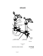
(3) Electric Pitch Trim:
Located on the pilot’s flight panel, the PITCH TRIM ENG / DISENG
switch engages or disengages the electric pitch trim. Pitch trim is
also engaged whenever the autopilot is engaged. With electric pitch
trim engaged (amber DISEN switch legend extinguished), pitch trim
can be adjusted through use of a split-half pitch trim switch
(sometimes referred to as a “beep” switch) installed on the outboard
grip of each control wheel. Switch positions are labeled NOSE
DOWN and NOSE UP. Inadvertent actuation of pitch trim, including
runaway, is minimized through the split-half switch design. In order
for the pitch trim to be actuated, both halves of the switch must be
simultaneously moved in the same direction.
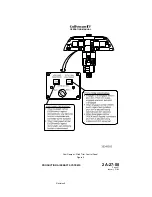
Movement of the electric pitch trim switch to NOSE DOWN or NOSE
UP actuates the autopilot elevator trim servo. The trim servo is
connected to the manual trim control wheel set by a chain. The
chain-driven movement of the manual trim control wheel set in turn
positions the elevator trim tabs.
The electric pitch trim is normally checked by the flight crew on the
first flight of the day, during the Before Starting Engines checklist. A
check usually consists of running the elevator trim fully up, then fully
down, using normal methods, i.e., using both halves of the switch
simultaneously. This is followed by attempting to run the pitch trim
using each half of the switch alone. Any movement resulting from
using either half of the switch alone indicates a malfunction that
should be corrected before flight. The check is concluded by setting
pitch trim for the takeoff Center of Gravity (CG) condition as
determined using the Airplane Flight Manual.
(4) Elevator Trim Tab Actuator Heat System:
Electrically-heated elevator trim tab actuators are incorporated on
airplanes SN 1380 and subsequent and SN 1000 through 1379
having ASC 342. These actuators are designed to alleviate frozen or
stiff trim tab actuators possible in extreme cold temperatures. The
system receives power from Phase C of the Left Main AC bus.
Operation of the system is automatic and transparent to the flight
crew.
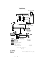
F. Angle-of-Attack / Stall Barrier System:
(See Figure 4, Figure 10 and Figure 11.)
While in flight, the Angle-of-Attack (AOA) system monitors aircraft AOA to
provide warnings of an approaching stall. If AOA continues to increase
toward aerodynamic stall, the system applies a nose down control input
through the stall barrier system.
The AOA / stall barrier system consists of the following units and
components:
OPERATING MANUAL
PRODUCTION AIRCRAFT SYSTEMS
2A-27-00
Page 10
January 31/02
Revision 6
Содержание IV
Страница 3: ...GIV Flight Controls Aerodynamic Axes Figure 1 OPERATING MANUAL 2A 27 00 Page 3 4 January 31 02 ...
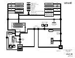
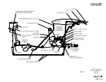
Страница 4: ...GIV Flight Controls Fluid Power Diagram Figure 2 OPERATING MANUAL 2A 27 00 Page 5 6 January 31 02 ...
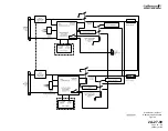
Страница 16: ...Stall Barrier Angle of Attack Wiring Schematic Figure 4 OPERATING MANUAL 2A 27 00 Page 19 20 January 31 02 ...
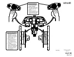
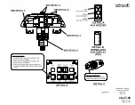
Страница 17: ...Pitch Trim Controls Figure 5 OPERATING MANUAL 2A 27 00 Page 21 22 January 31 02 ...
Страница 32: ...Rudder Pedals Forward Linkage Figure 13 OPERATING MANUAL 2A 27 00 Page 39 40 January 31 02 ...
Страница 50: ...Flaps Simplified Block Diagram Figure 18 OPERATING MANUAL 2A 27 00 Page 61 62 January 31 02 ...
Страница 51: ...Flaps Simplified Electrical Diagram Figure 19 OPERATING MANUAL 2A 27 00 Page 63 64 January 31 02 ...
Страница 65: ...Spoiler Speed Brake Controls and Indications Figure 23 OPERATING MANUAL 2A 27 00 Page 79 80 January 31 02 ...
Страница 66: ...Ground Spoiler Controls and Indications Figure 24 OPERATING MANUAL 2A 27 00 Page 81 82 January 31 02 ...


