2A-27-40: Roll Flight Control System
1. General Description:
Aircraft movement about the longitudinal axis (roll) is controlled by the position of
the ailerons. The ailerons are manually (control wheel) or electrically (autopilot
servo) controlled, mechanically actuated and hydraulically boosted airfoils
mounted on the trailing edge of each wing. Total aileron travel ranges from 10°
trailing edge up to 10° trailing edge down.
Each aileron is positioned by a tandem type hydraulic actuator. The actuator
receives hydraulic operating pressure simultaneously from both the Combined
and Flight hydraulic systems during normal operations. Loss of a single hydraulic
system has no effect on operation of the ailerons, as the remaining system is
capable of maintaining actuator load capacity. In the event of total loss of
hydraulic pressure in both systems, the ailerons revert to manual operation.
Manual reversion is also possible through use of a flight power shutoff valve and
its pedestal-mounted control handle.
Flight spoilers are incorporated into the roll flight control system to improve aircraft
roll response. During roll, the spoilers respond to upward movement of the
ailerons while the opposite spoilers remain flush to the wing as the opposite
aileron travels downward. Spoiler travel varies in proportion to the degree of the
roll, to maximum extension of 26
±
2° (55 +4/-3° with speed brakes extended). The
flight spoiler system is solely a hydraulically powered system, thus reversion to
manual control is not possible.
A roll trim system is used to position a trim tab attached to the trailing edge of the
left aileron. The tab is positioned manually by a pedestal-mounted control wheel.
On CAA certified aircraft, a flight control automatic failure detection system
monitors forces within the roll flight control system. If a malfunction is detected,
the system shuts off both hydraulic power sources to the affected actuator.
The roll flight control system consists of the following subsystems, units and
components:
•
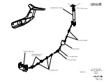
Control wheel system
•
Mechanical actuation system
•
Hydraulic boost system
•
Manual reversion system
•
Flight spoiler system
•
Roll trim system
•
Failure detection system (CAA aircraft only)
2. Description of Subsystems, Units and Components:
A. Control Wheel System:
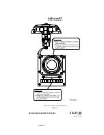
(See Figure 7.)
A control wheel mounted on top of the left and right control column is used
for roll control. Each control wheel has the following controls incorporated:
•
Pitch trim (NOSE UP / NOSE DOWN)
•
Map light (MAP)
•
Transponder identification (IDENT)
•
Touch control steering (TCS)
OPERATING MANUAL
PRODUCTION AIRCRAFT SYSTEMS
2A-27-00
Page 42
January 31/02
Revision 6
Содержание IV
Страница 3: ...GIV Flight Controls Aerodynamic Axes Figure 1 OPERATING MANUAL 2A 27 00 Page 3 4 January 31 02 ...
Страница 4: ...GIV Flight Controls Fluid Power Diagram Figure 2 OPERATING MANUAL 2A 27 00 Page 5 6 January 31 02 ...
Страница 16: ...Stall Barrier Angle of Attack Wiring Schematic Figure 4 OPERATING MANUAL 2A 27 00 Page 19 20 January 31 02 ...
Страница 17: ...Pitch Trim Controls Figure 5 OPERATING MANUAL 2A 27 00 Page 21 22 January 31 02 ...
Страница 32: ...Rudder Pedals Forward Linkage Figure 13 OPERATING MANUAL 2A 27 00 Page 39 40 January 31 02 ...
Страница 50: ...Flaps Simplified Block Diagram Figure 18 OPERATING MANUAL 2A 27 00 Page 61 62 January 31 02 ...
Страница 51: ...Flaps Simplified Electrical Diagram Figure 19 OPERATING MANUAL 2A 27 00 Page 63 64 January 31 02 ...
Страница 65: ...Spoiler Speed Brake Controls and Indications Figure 23 OPERATING MANUAL 2A 27 00 Page 79 80 January 31 02 ...
Страница 66: ...Ground Spoiler Controls and Indications Figure 24 OPERATING MANUAL 2A 27 00 Page 81 82 January 31 02 ...


