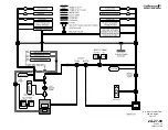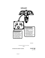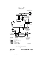
•
AOA probes
•
AOA display and approach indexer
•
Stall warning computers
•
Pilot and copilot control column shaker motors
•
Stall barrier system
AOA becomes fully functional as the aircraft becomes airborne, i.e., when
the nutcracker shifts to the AIR mode. The control column shaker, however,
is disabled for the first five seconds following rotation to eliminate nuisance
activity. Pulling the SHAKER #1 and / or SHAKER #2 circuit breakers, as
appropriate, is the only way to disable a control column shaker in flight;
however, such action completely disables the associated stall warning
computer(s). System design is such that either stall warning computer is
capable of operating the control column shaker and control column pusher
should the other computer become disabled.
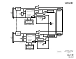
(1) AOA Probes:
An AOA probe / transducer assembly is installed on the left and right
forward fuselage. The cone-shaped probes freely rotate in the
airstream to provide AOA reference data for the stall warning / stall
barrier systems and AOA display data for the flight crew. The left
AOA probe provides data the No. 1 stall warning computer while the
right AOA probe provides data the No. 2 stall warning computer.
Heating elements prevent ice accumulation on the probe and
condensation within the transducer case.
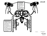
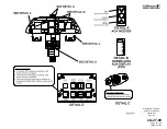
(2) AOA Display and Approach Indexer:
AOA display data supplied by the probes includes the normalized
AOA display and the approach indexer. Normalized AOA display is
shown on the lower left portion of the Primary Flight Display (PFD)
and consists of a vertical scale marked from 0.2 to 1.1 in 0.1
increments. At the bottom of the scale is a three-digit display
surrounded by a pointer that provides AOA indication within a 0.01
resolution. As AOA changes, the display / pointer moves up and
down to correspond with the indication on the scale.
An AOA approach indexer on either side of the windshield center
post indicates the optimum AOA for approach and landing. The No.
1 AOA system drives the pilot’s indexer while the No. 2 AOA system
drives the copilot’s indexer. During approach and landing, the AOA
system illuminates each indexer’s red chevron if AOA is too high, a
green circle if AOA is correct or an amber chevron if AOA is too low.
(3) Stall Warning Computers:
The No. 1 and No. 2 stall warning computers receive the following
inputs and then provide outputs to the control column shaker motors
and stall barrier system:
•
AOA reference data from the associated probes
•
Altitude data from the DADCs
•
Nutcracker mode from the nutcracker relays
•
Flaps position from the 39° flap relay
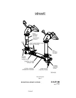
(4) Control Column Shaker Motors:
OPERATING MANUAL
PRODUCTION AIRCRAFT SYSTEMS
2A-27-00
Page 11
January 31/02
Revision 6
Содержание IV
Страница 3: ...GIV Flight Controls Aerodynamic Axes Figure 1 OPERATING MANUAL 2A 27 00 Page 3 4 January 31 02 ...
Страница 4: ...GIV Flight Controls Fluid Power Diagram Figure 2 OPERATING MANUAL 2A 27 00 Page 5 6 January 31 02 ...
Страница 16: ...Stall Barrier Angle of Attack Wiring Schematic Figure 4 OPERATING MANUAL 2A 27 00 Page 19 20 January 31 02 ...
Страница 17: ...Pitch Trim Controls Figure 5 OPERATING MANUAL 2A 27 00 Page 21 22 January 31 02 ...
Страница 32: ...Rudder Pedals Forward Linkage Figure 13 OPERATING MANUAL 2A 27 00 Page 39 40 January 31 02 ...
Страница 50: ...Flaps Simplified Block Diagram Figure 18 OPERATING MANUAL 2A 27 00 Page 61 62 January 31 02 ...
Страница 51: ...Flaps Simplified Electrical Diagram Figure 19 OPERATING MANUAL 2A 27 00 Page 63 64 January 31 02 ...
Страница 65: ...Spoiler Speed Brake Controls and Indications Figure 23 OPERATING MANUAL 2A 27 00 Page 79 80 January 31 02 ...
Страница 66: ...Ground Spoiler Controls and Indications Figure 24 OPERATING MANUAL 2A 27 00 Page 81 82 January 31 02 ...


