background image

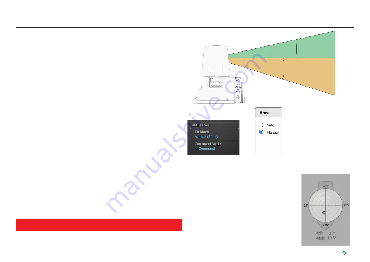
20° Scanner Tilt

16° Scanner Tilt

l


25

The scanner tilt mechanism automatically compensates for the pitch and roll of the vessel 

caused by wave motion.
Motion Sensors and a tilting optics mechanism ensure that the scanning optics remain at 

the correct level to see the scene.

Scanner Tilt Modes

The scanner can be operated in either of the following tilt modes:

• 

Auto - When starting tracking, the scanner will automatically “sweep” through a range of 

angles to determine the most stable scene for tracking purposes.

• 

Manual - This mode is used to manually tilt the optics to point at the scene. For 

example, when station-keeping close to a platform where the superstructure is high up 

and the SceneScan beam must be tilted upwards. When starting tracking, the scanner 

will initially use the currently selected angle. No “sweep” will be performed. Manual Tilt 

can also be used to visually survey the scene around the vessel without tracking. 

Once a suitable tilt angle has been chosen tracking will start and the scanner tilt angle will 

automatically adjust as the range to the asset changes. This is to ensure that the same part 

of the scene is used throughout the tracking session.
When the Sensor is rebooted the tilt mode defaults to Auto.
The current tilt mode and leveller angle are displayed in the ‘Tilt Mode’ section of the Side 

Bar.

To change the scanner tilt mode and leveller angle

1.  Click on the Tilt button in the Side Bar. 

2.  Select the required mode and click on the Apply button to confirm.
3.  Click on the +/- buttons to adjust the angle.  

4.  Click on the Apply button to confirm your changes.

Scanner Tilt Controls

Sidebar Tilt Mode section

Tilt Mode Selection

Once the scanner starts tracking, it is not possible to change the tilt mode or leveller 

angle

Spirit Level

The Spirit Level control, on the left hand side of the Tilt 

pane, displays the roll and pitch of the vessel as measured 

by the Vertical Reference Unit within SceneScan. The 

graphical display represents the roll and pitch angles in the 

same manner as a bull’s eye spirit level. The current values 

are displayed in text at the bottom of the control. A ship 

outline is shown in the background to indicate orientation 

relative to the vessel.

Содержание 20-0253

Страница 1: ...iber Way Meridian Business Park Leicester LE19 1QP UK T 44116 229 2600 E sales guidance eu com www guidance eu com www marine direct W A R R A N T Y See our standard terms of sale Q U A L ITY ASSUR E...

Страница 2: ...may not be used sold transferred copied or reproduced in whole or in part in any manner or form or in or on any media to any person other than in accordance with the terms of the Owner s Agreement or...

Страница 3: ...he Dynamic Blanking Zone 24 Scanner Tilt Controls 25 Scanner Tilt Modes 25 Spirit Level 25 Tracking 26 To Start Tracking 26 To Stop Tracking 26 Adjusting the Scene Reference Point 27 Enabling DP Outpu...

Страница 4: ...Installing SceneScan Client Software onto a Computer 56 Upgrading the Sensor Software 57 Configuring the SceneScan System 58 Using the Service Interface 59 Network Communication Settings 60 Vessel Pa...

Страница 5: ...l 5 Introduction This section provides an introduction and overview of the SceneScan system It contains the following sections Welcome page 6 System Overview page 7 SceneScan Sensor Part Names page 8...

Страница 6: ...xplains how to Use the SceneScan system Physically install the system Install and operate the Dashboard software Install the Service Interface Note Installation of a SceneScan system should be carried...

Страница 7: ...Interface The SceneScan Service Interface is used for system installation and maintenance The SceneScan Dashboard The SceneScan Dashboard generates a visual representation of the scene detected by the...

Страница 8: ...iagram below shows the key parts of the Sensor unit and the various names that are used throughout this guide Optical Window Rotor Base Plate Sensor Information Display Access Plate Cable Gland Plate...

Страница 9: ...ted This section contains the following pages Start Up and Shut Down page 10 Targetless Tracking page 11 Screen Layout page 13 Tracking Information Quality page 19 Display Settings page 20 Vessel Orie...

Страница 10: ...t Down To Suspend Exit or Disconnect 1 Click on the Guidance button in the lower left corner of the screen This will reveal buttons in the side bar as follows see right Suspend Places the Sensor into...

Страница 11: ...suitable section has been selected the system starts tracking and reporting the position of the Sensor within the scene As the Sensor moves and the view of the scene changes the Sensor will automatica...

Страница 12: ...ill start reporting its position relative to the Scene Reference Point By default SceneScan will select the centre of the tracked scene for the scene reference point with a heading of 0 This behaviour...

Страница 13: ...l 13 Screen Layout The SceneScan Dashboard screen is split into three distinct sections these are 1 Main Screen and Bird s Eye View BEV see page 14 2 Side Bar see page 16 3 Menu Pane see page 18...

Страница 14: ...pe of the vessel outline and the position of the Sensor s red dot within it can be configured using the SceneScan Service Interface Blanking Zone The Blanking Zone is an area defined by the user in or...

Страница 15: ...ng logged to disk Zoom Control Allows a user to zoom in and zoom out of the BEV Click on the left hand side of the control marked to zoom out of the display and on the right hand side to zoom in Syste...

Страница 16: ...ains control and display components in addition to the coordinates panel After pressing the Guidance button Toggle Coordinate Type Signal Quality Coordinate Data DP Message Format Current Tilt Mode an...

Страница 17: ...between displaying a traditional circular BEV or Full Scene mode F9 Toggle between the day view and night view F10 Capture a screenshot of the Dashboard interface and save it to disk F11 Toggle betwee...

Страница 18: ...ot always visible It appears when one of the Tracking Tilt or Advanced buttons near the foot of the Side Bar are pressed which causes the Bird s Eye View BEV to contract towards the top of the screen...

Страница 19: ...size of the filled portion of the Data Quality Bar the greater the level of confidence in the information The colour of the Data Quality Bar and positional data also reflects the level of confidence...

Страница 20: ...een Brightness control To change day night mode and adjust brightness 1 Navigate to Advanced Display Options Display Settings 2 Click on one of the Day Night Mode symbols 3 Click on the left side of t...

Страница 21: ...hotkey The latter is useful when viewing complex scenes such as harbours The BEV can be further expanded to a full screen mode by pressing F11 or using the Toggle Full Screen hotkey This mode maximise...

Страница 22: ...e to Advanced Display Options Layout 2 Click on the vessel outline that points in the required direction Note Changes made to the vessel orientation using the Dashboard are temporary and will revert b...

Страница 23: ...l 23 Tracking Basics This section contains the following pages Dynamic Blanking Zone page 24 Scanner Tilt Controls page 25 Tracking page 26 Positional Display Modes page 29...

Страница 24: ...namic blanking zone 1 Click one of the dynamic blanking zone handles and holding down the left mouse button drag to the desired position Alternatively on a touchscreen touch and drag As the handle is...

Страница 25: ...scanner tilt angle will automatically adjust as the range to the asset changes This is to ensure that the same part of the scene is used throughout the tracking session When the Sensor is rebooted th...

Страница 26: ...erator user selects the tilt angle To Stop Tracking While tracking is in progress a Stop button is nestled within the Tracking button Click on the Stop button to stop tracking Tracking To Start Tracki...

Страница 27: ...e that the Dashboard is In Command see In Command Mode on page 33 and is Tracking It does not matter whether DP Feed is enabled or not 2 Press the Tracking button to bring up the Tracking Menu 3 Press...

Страница 28: ...be changing significantly during a tracking session 5 When tracking off a rig substructure tends to provide more robust tracking performance than superstructure Enabling DP Output Once tracking the da...

Страница 29: ...earing Heading Range Bearing and Heading R B H mode displays the distance and the bearing of the Scene Reference Point from the Sensor The radial markers around the outside of the BEV are zeroed in li...

Страница 30: ...A and B Axes A Pos and B Pos In this mode the position of the Sensor vessel is expressed in metres from the scene along A and B axes which have their origin at the Scene Reference Point The vessel s r...

Страница 31: ...l 31 Multi Dashboard SceneScan Systems This section contains the following pages SceneScan Dashboard Monitoring Mode page 32 SceneScan Dashboard In Command Mode see page 33...

Страница 32: ...e of these can be in Command mode at any given time the others are in Monitoring mode When the Dashboard is running in Monitoring mode the controls relating to the Dashboard itself will be active but...

Страница 33: ...n Command When the In Command Dashboard is used to suspend the SceneScan Sensor a message will appear on the screens of the Monitoring Dashboards indicating that the system is suspended The same messa...

Страница 34: ...ection contains the following pages Low Temperature Operation page 35 Working with Alarms page 36 Dynamic Positioning Feed page 37 Network Communications Settings page 38 Data Logging page 39 Seial Nu...

Страница 35: ...ut will require 2 hours to reach optimum operating condition If the unit is switched on after a period at temperatures between 15 to 25 C it will not communicate with the Dashboard and the rotor will...

Страница 36: ...rrent state of an alarm are reflected in its colour and shape Information grey symbols Warning orange symbols Error and Fatal red symbols The Play symbol indicates that an alarm condition is persistin...

Страница 37: ...s However this cannot be done from the Dashboard in order to change the SceneScan DP settings use the SceneScan Service Interface see page 66 for the Dynamic Positioning Feed Configuration and See pag...

Страница 38: ...dashboard but IS possible from the SceneScan Service Interface Network Config tab Sensor on board network configuration section See page 59 for the Network Communication Settings To View the Network C...

Страница 39: ...Or 1 Click on the Hotkeys tab 2 Click on the Stop Manual Data Log button Or Click on the flashing Data Logging Indicator in the top left of the main screen Or Manual logging automatically stops when...

Страница 40: ...the current screen and stores it at the same location as the data logs Up to ten screenshots are held and if a further screenshot is taken the oldest of the existing ten is automatically deleted To ta...

Страница 41: ...rvice support call to the company Software Version Information The About tab of the SceneScan Service Interface displays software version information and the Sensor serial number SceneScan Sensor Prod...

Страница 42: ...customerservices us guidance eu com Asia Support 65 6734 6365 customerservices sg guidance eu com Web www guidance eu com customer support How to report issues By reporting issues with enough informa...

Страница 43: ...l and ensure that no pulses from the vessel structure are observed outside of the vessel outline in the Dashboard System appears to be operational but no scene is displayed when the Sensor is close en...

Страница 44: ...it in and turn it anti clockwise until the insert releases and can be pulled out Reverse the above procedure to replace the fuse Both fuses have the same specification Live Neutral Ensure the replacem...

Страница 45: ...l 45 Installing the SceneScan Hardware This section contains the following pages Where to Mount the Sensor page 46 Sensor Dimensions and Mounting Template page 47...

Страница 46: ...ear of VHF emergency band antennae S band and X band ship s radars 5 meter minimum horizontal separation from RF sources VHF S and X band and ideally vertical separation of one deck Clear of likely em...

Страница 47: ...e baseplate horizontally 300 150 150 705 857 150 47 405 360 327 190 80 407 4 x 9 THRU Allow 300mm clearance at the access plate to manoeuvre internal assemblies in out Allow 150mm clearance at either...

Страница 48: ...ables This section contains the following pages Cable Specifications page 49 UPS Specifications page 50 SceneScan Sensor Connections page 51 SceneScan Client and DP Feed Connections page 52 Cable Rout...

Страница 49: ...s from 7 13mm diameter All cables should be External marine standard including UV and chemical resistance 500V rated voltage Diameter 7 13mm Operate between 30 C to 70 C Cable Description Guidance Mar...

Страница 50: ...t 110V 1 2A RMS Peak Current draw at 230V 0 7A Nominal Current draw at 230V 0 6A RMS The SceneScan UPS should be able to run on back up power for at least the same duration as that specified for the D...

Страница 51: ...board See SceneScan Sensor Part Names on page 8 2 Remove the screw head from the appropriate watertight cable gland See SceneScan Sensor Part Names on page 8 to identify the correct cable gland 3 Fee...

Страница 52: ...nnector hole in plug 3 3 Whilst holding down lever insert cable end into connector hole Release and remove the lever tool RS422 Link to DP System 1 1 GND 2 RX 3 RX 4 TX 5 TX DP Feed 2 Serial 0 SceneSc...

Страница 53: ...wer Cable P N 33 0121 3 40m Ethernet Cable P N 33 0124 3 40m 16A 5A 5A DP System UPS SceneScan Sensor Link Cable SceneScan Client DP Feed Power SceneScan Monitor Monitor Power Cable Monitor Cable Scen...

Страница 54: ...tteland Touchscreen Monitor Processor or Type 3 Marine Processor Part Number 20 0280 Monitor Hatteland Marine Touchscreen Monitor Part Number 20 0211 4 Optional brackets Hatteland Mounting Bracket Par...

Страница 55: ...information For a Type 3 Marine Processor 94 0465 4 Type 3 Marine Processor and Display Installation Sheet For a Hatteland Panel PC 94 0466 4 Hatteland Panel PC Installation Sheet The following pages...

Страница 56: ...re 1 Locate the files SceneScanDashboardSetup exe and SceneScanServiceInterfaceSetup exe on the USB memory stick on which they were supplied 2 Double click on the SceneScanDashboardSetup exe file The...

Страница 57: ...neScan Installer Remote exe on the USB memory stick on which the SceneScan software was supplied 3 Double click on the SceneScan Installer Remote exe file 4 Enter the Sensor s IP Address 5 Click on th...

Страница 58: ...ork Communication Settings page 60 Vessel Parameters page 62 Static Blanking Zones page 65 Dynamic Positioning Feed Configuration page 66 DP Feed Behaviour page 67 System Parameters page 69 DP Message...

Страница 59: ...nd control buttons Connected State Whether the SceneScan Service Interface is Connected to the Sensor or Disconnected Sensor State System Running Normally or System Suspended when the SSI is connected...

Страница 60: ...Click on the Edit button 4 Alter the settings as required 5 Click on Apply to save the changes or on Cancel to discard To Modify the Sensor s On Board Network Configuration There are two options to m...

Страница 61: ...ini 2 Click on theTake Command button if the SceneScan Service Interface is not already In Command 3 Click on Browse 4 Locate the connect ini file within the Select a Sensor network configuration file...

Страница 62: ...default direction of the vessel bow as displayed on the Bird s EyeView of the Dashboard Changing this setting rotates the whole BEV but does not affect the data sent to the DP system Note that this s...

Страница 63: ...starboard Sensor perpendicular to vessel centre line Bearing Offset 90 Sensor Facing Starboard Connection panel facing port Sensor perpendicular to vessel centre line Bearing Offset 270 180 270 90 0...

Страница 64: ...tab click on the Defaults button To Import Vessel Calibration from a File 1 Click on the Resume button if the Sensor is supended 2 Ensure that no tracking is in progress 3 Click on theTake Command bu...

Страница 65: ...egrees In order to distinguish one zone from another clicking on a Show Zone n button will cause the corresponding zone to be displayed in a different colour along with the button itself Modifying the...

Страница 66: ...t recent message emitted See DP Message Types page 70 for details of each available message format and DP Feed Behaviour page 66 for details about each of the function of the Keep Feed Enabled and All...

Страница 67: ...te Idle System State Not Tracking No Output No Output Zero Positional Data Invalid Status No Output DP Feed State Idle System State Tracking and DP Feed Output Disabled No Output No Output Fresh Posit...

Страница 68: ...hm calculates 3 Stale positional data refers to the last set of valid range and bearing values that the tracking algorithm calculated 4 Valid status means that the positional data in the DP Feed outpu...

Страница 69: ...File Selection window locate the xml file you wish to import 7 Click the Open button 8 Wait for the message box to inform you that the import has been successful To Export 1 Click on the Resume butto...

Страница 70: ...d 2 Ensure that the Sensor is not currently tracking 3 Click on theTake Command button if the SceneScan Service Interface is not already in Command 4 Click on the ParametersTab 5 Click on the Edit but...

Страница 71: ...LF Line feed ASCII 0A hex NMEA0183P Format A 42 character string RLS AAA AA BBB BB S1 XXX XXX S2 HHHH CC CR LF Where RLS message header AAA AA resolved primary position in A axis metres BBB BB resolv...

Страница 72: ...m in hex CC 20 Carriage Return X 21 Line Feed 0x0Ah X DP Message Types Continued Nautronix Standard A 14 character string delimited only by CR and LF with bearing measured bow clockwise Character Inde...

Страница 73: ...5 chars E Sequence identifier 1 char IIII I Scene Reference Point ID 1 char S Status V oid or N avigating 1 char RRR R RR Range in metres 4 7 chars ZR ZRZR Range standard deviation in metres 4 chars...

Страница 74: ...rs S Status V oid or N avigating 1 char RRR R RR Range in metres 4 7 chars ZR ZRZR Range standard deviation in metres 4 chars BB B BB Bearing in degrees clockwise from bow 4 6 chars ZB ZBZB Bearing st...

Страница 75: ...prietary header 6 chars II Scene Reference Point ID 2 chars RRRR R Range in meters 6 chars ZR ZR Range Standard Deviation in meters 3 chars BBB B Bearing in degrees 5 chars ZB ZB Bearing Standard Devi...

Страница 76: ...follow the instructions for Rotor Optics Tilt Drive Belt Replacement of the Rotor Drive Belt Spring Tensioned or Replacement of the Rotor Drive Belt Non Spring Tensioned All maintenance items should...

Страница 77: ...r details and vessel calibration by performing angle sweep from dashboard and seeing vessel structure is contained within vessel outline Check Requirement Checked Initial Notes record setting Mechanic...

Страница 78: ...tkeys 17 How to report issues 42 I Installation 56 57 K Kongsberg 72 75 M MDL Multi Scene 72 Standard 72 Moitoring 32 Monitoring 45 MT Custom DP String 73 N Nautronix Standard 72 Network Communication...

Страница 79: ...79 T Temperature 35 Toggle BEV Shape 15 21 Tracking Overview 11 23 Starting and Stopping 26 Tilt Controls 25 Troubleshooting 43 U UPS Specifications 50 V Version 41 Vessel Parameters 62 Index Continue...

Страница 80: ...l 80 Document History Document Number Changes Issue Date 94 0561 A First release of SceneScan User s Guide 11 05 2018 94 0561 B Section added How to report issues 17 12 2018...

Страница 81: ......

Отзывы: