background image


 Installation & User Manual – Oncam C-12 Series 


© 

Oncam Global Group AG, 2021. All rights reserved. 

24 


Figure 32 Clipping of Front Cover


Clip the front cover onto the camera module lens 

surround, make sure the tether is folded in out of 

the way.


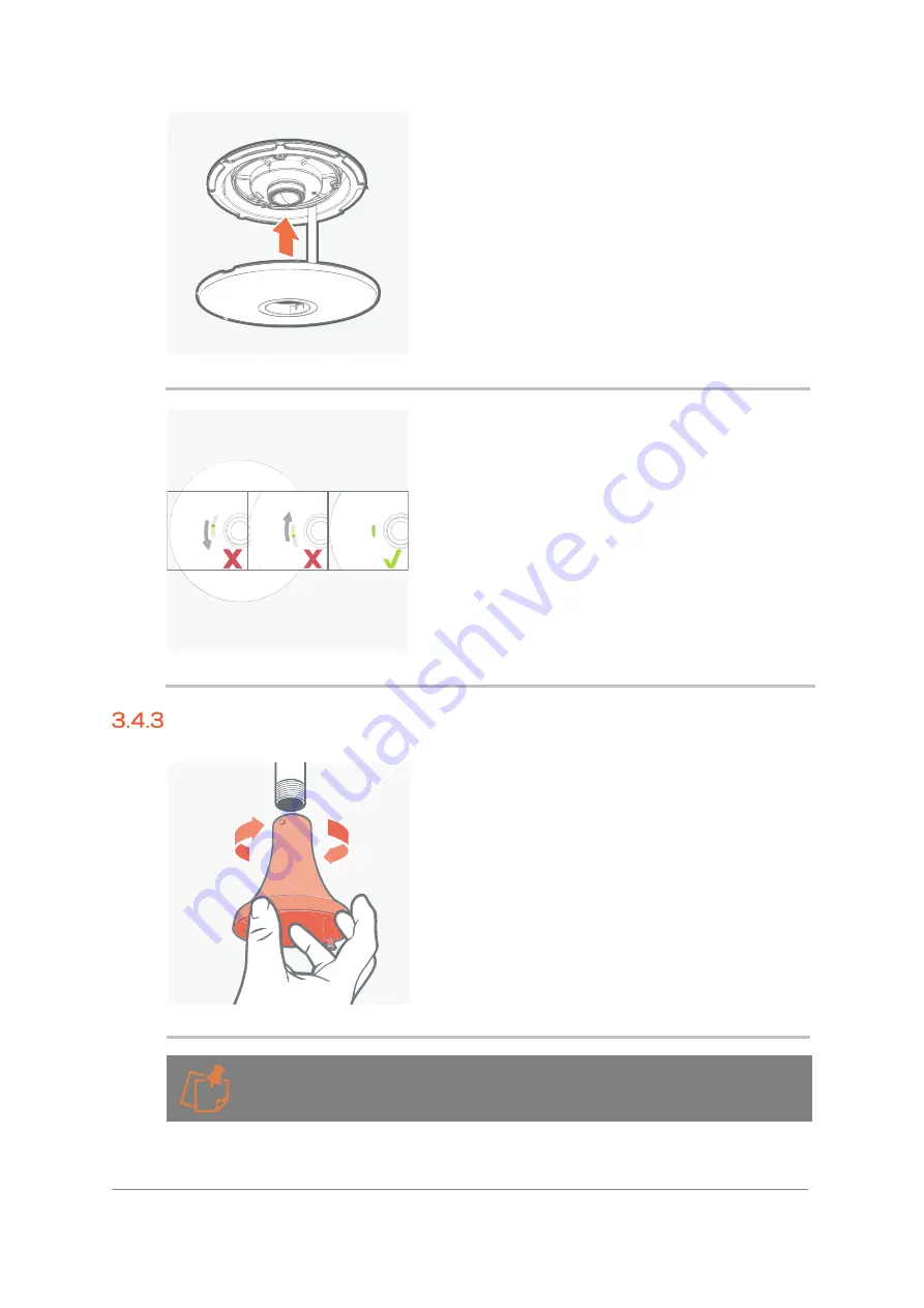
Figure 33 Slot Alignment with LED


Align the slot with the Status LED for the best view.


Pendant Mounting 


Figure 34 Pendant Mount


Run a drop conduit using external (male) thread 

M20 or 3/4" NPT conduit. The pendant mount will 

screw directly onto the conduit.


The two thread sizes use the same hole. 


Содержание Onvif Oncam C-12 OUTDOOR PLUS

Страница 1: ...Installation and User Manual Oncam C 12 C 12 OUTDOOR PLUS C 12 INDOOR INSTRUCTION MANUAL C 12 006 0064 0538 Rev 6 ...

Страница 2: ...nection 12 Indoor Camera 12 Outdoor Plus Camera 36 SD Card Support 74 Uninstalling and Returns 75 4 Camera Access 79 First Time Access Discovery 79 First Time Access Set Primary Administrator Username and Password 81 5 Camera Configuration 85 Dashboard Camera Web Interface 85 Network 89 Video Audio Streaming 95 Recording 151 Events 161 Motion Analytics 172 Users 183 Device 187 Peripherals 209 6 Tec...

Страница 3: ...product does not contain any parts which are user serviceable Liability Notice Every care has been taken in the preparation of this and the accompanying installation documentation Oncam Global Group AG 2013 2020 All rights reserved No part of this manual may be reproduced except for your express personal use Oncam and their affiliate s further reserve the right to alter amend or revise this docume...

Страница 4: ...d using a shielded network cable STP that is properly grounded 1 1 6 3 USA This device complies with part 15 of the FCC Rules Operation is subject to the following two conditions 1 This device may not cause harmful interference and 2 This device must accept any interference received including interference that may cause undesired operation This equipment has been tested to comply with the limits f...

Страница 5: ...on point contact your local authority responsible for waste disposal Businesses should contact the product supplier for information about how to dispose of this product correctly This product complies with the requirements of Directive EU 2015 863 on the restriction of the use of certain hazardous substances in electrical and electronic equipment RoHS Contact Information For our contact details pl...

Страница 6: ...ce Dynamic Discovery Multicast UDP 12345 UDP 12346 Oncam Probe Table 1 Port Pre Configuration Safety Information 1 1 13 1 Hazard Levels CAUTION Indicates a hazardous situation which if not avoided could result in minor or moderate injury or property damage RISK OF EXPLOSION If components are replaced incorrectly SHARP Indicates cautionary warning of sharp edge or object 1 1 13 2 Iconography Note I...

Страница 7: ...crushed or pinched particularly at plugs convenience receptacles and the point where they exit from the apparatus Direct DC Input Use only a UL CSA approved LPS or NEC Class 8 28 VDC 15W LPS power supply not supplied The power source must be connected with the correct polarity Do not use an excess of 28 VDC from an external power supply Doing so may damage the camera and void the warranty 1 1 14 2...

Страница 8: ...ard 1 1 14 6 Dome Handling and Cleaning The standard dome is made of a polycarbonate PC polymer Take care when handling or cleaning the dome to avoid scratching the surface Always handle the dome by the outside edge of the flange or trim ring assembly Avoid contacting inside surface of the dome Remove dust or other surface contaminants from the dome s interior with clean dry air pressure compresse...

Страница 9: ...Web Interface the user has quick and easy access to Camera Modes media streaming profiles StreamLite compression TrueDetail HDR and Advanced Light Management settings This ensures the delivered stream has the desired image quality level resolution frame rate and bandwidth The Oncam Camera Configuration Tool uses the same sleek user interface and enables advanced management of the C Series cameras ...

Страница 10: ... g High Speed or Multiple streaming OSD masks saved by Image output mode e g Fisheye Panoramic and Multi Mode The following settings need to be configured when the camera module is in the correct final housing Media profiles Metadata settings Events The Camera module will need to be in outdoor housing for Plus feature recognition and configuration of the following settings Actions Triggers H W Inp...

Страница 11: ...ignage Wall Mount Wall mounting the camera can give a complete 180 degree side on view of an area Use this view where ceiling mounting is not possible or if you need to capture a higher level of detail for objects closer to the camera such as people s faces as they walk past the camera Table Mount Mount the Table Mount camera on a flat surface looking up While this mount is for demonstration or te...

Страница 12: ...UL CSA approved LPS or NEC Class 8 28 VDC 15W LPS power supply not supplied The power source must be connected with the correct polarity Do not use an excess of 28 VDC from an external power supply Doing so may damage the camera and void the warranty RJ45 and Punch Down For increased flexibility during camera installation two methods of connection to the Oncam C 12 camera are available RJ45 and Pu...

Страница 13: ...e ethernet cable Figure 2 Opening of Camera Enclosure Open camera enclosure Figure 3 Mounting of Camera Enclosure Mount the rear of the camera enclosure to the wall with the screws not provided with the product The camera has been designed to be mounted with 8 or 4mm countersunk screws however the length and fixing support material plugs etc need to be specified by the installer on a case by case ...

Страница 14: ...efer to use the punch down you need to add the punch down adapter here accessory located in the box packaging Following the guide punch down the ethernet cable Figure 5 Identify Wiring Type for Punch Down Strip sheath to approximately 7cm 2 3 4 So you have enough wires to punch down excess wire can be cut after punching down CLICK ...

Страница 15: ...bstruct the camera module After wires are punched down cut off any excess wires Figure 7 Protective Cover Removal Remove and recycle the protective cover from the rear of the camera module Figure 8 Connecting of Camera Module Connect the camera module the clips will hold the camera in place For RJ45 simply plug the camera module in for the punch down simply connect the camera CLICK ...

Страница 16: ...l Group AG 2021 All rights reserved 16 Figure 9 Connecting of Ethernet Cable Figure 10 Securing the Camera Module Using the security hex tool tighten the 3 captive screws Figure 11 Protective Lens Cover Removal Remove and recycle the protective lens cover ...

Страница 17: ...to work with sheet material such as plasterboard There is no minimum sheet thickness only it requires flat material however the spring retaining strength will be weaker the thinner the material is The springs will retain the camera material up to a maximum 25mm 1 thick Figure 13 Drilling Hole After selecting a suitable position drill a 100mm 4 hole Figure 14 Feeding Ethernet cable to the hole Feed...

Страница 18: ...45 Punch down Identify which type of connection you want to use RJ45 or punch down remove the outer plug for RJ45 and the center plug for punch down Figure 16 Snipping of Support tabs for Punch down Using wire cutters carefully snip two of the support tabs Figure 17 Snipping of Support tab for Ethernet Cable Sharp Edges ...

Страница 19: ...liers Use pliers to twist and remove the plug Sharp Edges Figure 19 Inserting of Grommet Being careful watching for sharp edges insert the grommet to protect the wire and to make cut edges safe Figure 20 Mount Screws Removal Remove the two mount screws put to one side These will be used later to mount the rear camera enclosure ...

Страница 20: ...or Enclosure Opening Open the indoor enclosure dispose of and recycle the plastic front cover Figure 22 Inserting Punch down adaptor Punch down only insert the punch down adaptor accessory located in the box packaging and punch down the ethernet cable using the guide Figure 23 Punch down Ethernet cable CLICK ...

Страница 21: ...ing Type for Punch Down Strip sheath to approximately 7cm 2 3 4 So you have enough wires to punch down excess wire can be cut after punching down Figure 25 Punch Down Wires If using punch down press the wires down to ensure they do not obstruct the camera module After wires are punched down cut off any excess wires ...

Страница 22: ...nto Recessed Mount Insert the rear of the enclosure into the recessed mount and screw it down with the two mount screws removed earlier Figure 27 Protective Cover Removal Remove and recycle the protective cover from the rear of the camera module Figure 28 Plug in RJ45 Cable RJ45 Only If the RJ45 cable is to be used plug it in now ...

Страница 23: ...ty screws to hold it in place There are arrows that aid alignment Figure 30 Securing of Recessed Enclosure into the Ceiling Taking the two retaining springs in each hand open them backwards and gently push into the hole drilled earlier This will then pull the recessed enclosure into the hole The camera can be aligned for the correct view if required Figure 31 Protective Lens Cover Removal Remove a...

Страница 24: ...ra module lens surround make sure the tether is folded in out of the way Figure 33 Slot Alignment with LED Align the slot with the Status LED for the best view Pendant Mounting Figure 34 Pendant Mount Run a drop conduit using external male thread M20 or 3 4 NPT conduit The pendant mount will screw directly onto the conduit The two thread sizes use the same hole ...

Страница 25: ...duit and through the pendant mount Figure 35 Mounting Screws Removal Remove and retain the two mounting screws These will be used later to mount the rear camera enclosure Figure 36 Opening of Camera Enclosure Open the camera enclosure Figure 37 Punch Down Adaptor Punch down only insert the punch down adaptor accessory located in the box packaging CLICK ...

Страница 26: ...l rights reserved 26 Figure 38 Punch Down Ethernet Cable Punch down the ethernet cable using the guide Figure 39 Identify Wiring Type for Punch Down Strip sheath to approximately 7cm 2 3 4 so you have enough wires to punch down Excess wire can be trimmed after punching down ...

Страница 27: ...a module After wires are punched down cut off any excess wires Figure 41 Secure Camera Enclosure onto the Pendant Mount Screw the rear of the camera enclosure to the pendant mount using the two mounting screws Make sure the ethernet cable pulls through the mounted rear of the camera enclosure Figure 42 Protective Cover Removal Remove and recycle the protective cover from the rear of the camera mod...

Страница 28: ...re all three clips are fully engaged Tighten the 3 captive security screws to fix the camera module securely in place Figure 44 Camera Image Alignment Using the marker on the rear of the camera housing as a reference align the pendant mount for the desired image orientation There is a top to the camera image represented by this marker it is recommended that this directional top is used to orientat...

Страница 29: ...ew thread Figure 46 Protective Lens Cover Removal Returning to the camera module remove and recycle the protective lens cover Figure 47 Align and close the Camera Enclosure Front Cover Using the alignment marker push the camera enclosure cover over the camera module and twist to lock in place Panoramic Tilt Mount Surface Mounting Using a spirit level to make sure it is straight affix the drilling ...

Страница 30: ...all Figure 48 Drilling Template Using the appropriate size of drill bit drill the mounting holes and the hole for the ethernet cable Remove the drilling template once drilled Figure 49 Remove Card Insert Unscrew the two mount screws and retain to mount the camera Recycle the card insert Ø10mm Ø 3 8 Ø16mm Ø 5 8 007 0114 0559 REV 1 0 FI X I N G CSK N º8 O R M4 RJ45 I N STA LLATI O N PU N CH D OWN I ...

Страница 31: ...1 Figure 50 Mount to wall Using 3 off Screws mount the bracket to the wall using the holes drilled previously Figure 51 Opening of Camera Enclosure Open camera enclosure Figure 52 Mounting of Camera Enclosure Mount the rear of the camera enclosure to the bracket with the screws retained above ...

Страница 32: ...efer to use the punch down you need to add the punch down adapter here accessory located in the box packaging Following the guide punch down the ethernet cable Figure 54 Identify Wiring Type for Punch Down Strip sheath to approximately 7cm 2 3 4 So you have enough wires to punch down excess wire can be cut after punching down CLICK ...

Страница 33: ...bstruct the camera module After wires are punched down cut off any excess wires Figure 56 Protective Cover Removal Remove and recycle the protective cover from the rear of the camera module Figure 57 Connecting of Camera Module Connect the camera module the clips will hold the camera in place For RJ45 simply plug the camera module in for the punch down simply connect the camera CLICK ...

Страница 34: ...l Group AG 2021 All rights reserved 34 Figure 58 Connecting of Ethernet Cable Figure 59 Securing the Camera Module Using the security hex tool tighten the 3 captive screws Figure 60 Protective Lens Cover Removal Remove and recycle the protective lens cover ...

Страница 35: ...move the label from the side of the angle mount exposing the security hole to allow the angle to be set Figure 63 Hex Tool Unlocks Using the hex tool used for mounting the camera screws push it in the hole on the side This will unlock the catch on the inside of the mount and allow the camera angle to be carefully adjusted There are physical and audible clicks at each 5 degree set angle 20 45 20 45...

Страница 36: ...ont is loose open the camera enclosure and undo the retaining tether Put the front enclosure back in the box for safe keeping Using a spirit level to make sure it is straight affix the drilling template to the wall by removing the self adhesive backing If you are concerned about the adhesive on a delicate surface put the drilling template on work trousers or other cloth to make it less sticky Usin...

Страница 37: ...uitable for these fixings and the larger hole for the ethernet cable then carefully remove the drilling template from the wall Figure 67 Gland Identification Remove the gland from the rear enclosure the two glands are highlighted with icons to denote which one should be used This is the one for the ethernet cable Figure 68 Removal of Gland ...

Страница 38: ...e with a terminated RJ45 connector use the RJ45 cap to protect the gland from damage and pull though 12cm 4 3 4 of cable Remove the cap For Punch down pull though 6cm 2 1 2 Pull the cable backwards to flip the seal inside out to ensure the seal is at its best Figure 70 Gland into Rear Enclosure Push the gland back into the rear enclosure ensure it is bedded back into place Figure 71 Check position...

Страница 39: ...appropriate fixings for the surface mount the rear enclosure to the wall The camera has been designed to be mounted with 8 or 4mm countersunk screws however the length and fixing support material plugs etc need to be specified by the installer on a case by case basis Figure 74 Plugging RJ45 Connector to RJ45 Socket If a cable terminated with a RJ45 connector is used then plug it into to RJ45 socke...

Страница 40: ...s reserved 40 Figure 75 Removal of RJ45 Board If using the punch down remove the RJ45 board and replace it with the punch down board accessory located in the box packaging Figure 76 Insert Punch Down Board Figure 77 Punch Down Ethernet Cable Strip and punch down the ethernet cable ...

Страница 41: ...entify Wiring Type for Punch Down Strip sheath to approximately 6cm 2 1 2 so you have enough wires to punch down Excess wire can be trimmed after punching down After wires are punched down cut off any excess wires Figure 79 Protective Film Removal Remove and recycle the protective film from the thermal pad ...

Страница 42: ...ve cover from the rear of the camera module Figure 81 Camera Module Connection Connect the camera module the clips will help to hold the camera in place Tighten the 3 captive screws using the hex tool Ensure all three clips are correctly engaged Figure 82 Reattach Front Cover Taking the front of the enclosure which was set aside reattach the retaining tether ...

Страница 43: ...he Front Cover With care place the front of the camera enclosure onto the rear of the enclosure and tighten the 3 captive security screws using the hex tool Figure 85 Protective Cover Removal Remove and recycle the protective film from dome Pendant Mount Kit Including Sunshield Run a drop conduit or pendant arm with an internal female 1 NPT thread Run the ethernet cable through the conduit ...

Страница 44: ...et cable through the central hole on the pendant mount screw the pendant mount to the 1 NPT thread Figure 87 Removal of Mounting Screws Remove the 3 mounting screws and put to one side These will be used later to mount the rear camera enclosure Figure 88 Loosen Captive Screws The camera comes assembled using the security hex bit loosen the 3 captive screws ...

Страница 45: ...front is loose open the camera enclosure and undo the retaining tether Put the front enclosure back in the box for safe keeping Figure 90 Gland Identification Remove the gland from the rear enclosure the two glands are highlighted with icons to denote which one should be used this is the one for the ethernet cable Figure 91 Removal of Gland ...

Страница 46: ...e with a terminated RJ45 connector use the RJ45 cap to protect the gland from damage and pull though 12cm 4 3 4 of cable Remove the cap For Punch down pull though 6cm 2 1 2 Pull the cable backwards to flip the seal inside out to ensure the seal is at its best Figure 93 Gland into Rear Enclosure Push the gland back into the rear enclosure ensure it is bedded back into place Figure 94 Check Position...

Страница 47: ...ure the tabs of the gland are aligned as shown Figure 96 Secure Rear Enclosure to the Pendant Mount Screw the rear enclosure to the pendant mount using the 3 screws removed from the pendant mount previously Figure 97 RJ45 Connector into RJ45 Socket If using a cable terminated with RJ45 connector plug it into to RJ45 socket ...

Страница 48: ... 48 Figure 98 Removal of RJ45 Board If using the punch down remove the RJ45 board and replace it with the punch down board accessory located in the box packaging Figure 99 Insert Punch Down Board Figure 100 Punch Down of Ethernet Cable Strip and punch down the ethernet cable using the guide ...

Страница 49: ...entify Wiring Type for Punch Down Strip sheath to approximately 6cm 2 1 2 so you have enough wires to punch down Excess wire can be trimmed after punching down After wires are punched down cut off any excess wires Figure 102 Protective Film Removal Remove and recycle the protective film from the thermal pad ...

Страница 50: ...ule the clips can help hold the camera in place Ensure all three clips are correctly engaged Tighten the 3 captive screws using the hex tool Figure 105 Camera Module Alignment Using the arrow on the camera module as a reference align the pendant mount for the desired image orientation There is a top to the camera image represented by direction of this arrow it is recommended that this directional ...

Страница 51: ...re 106 Reattach the front cover Taking the front of the enclosure which was set aside reattach the retaining tether Figure 107 Protective Lens Cover Remove and recycle the protective lens cover Figure 108 Secure Front Enclosure With care place the front of the camera enclosure onto the rear of the enclosure and tighten the 3 captive security screws using the hex tool ...

Страница 52: ...User Manual Oncam C 12 Series Oncam Global Group AG 2021 All rights reserved 52 Figure 109 Protective Film Remove and recycle the protective film from dome Figure 110 Camera after installation Completed installation ...

Страница 53: ...ing Screw Using the hex bit included in the box unscrew the locking screw The screw is captive and therefore will not fall out During the installation it is important not to allow the ethernet cable to twist Therefore it s important to take the tilt adaptor apart Figure 112 Run Ethernet Cable With the two halves apart run the ethernet cable through the center of the tilt adaptor Figure 113 Screw T...

Страница 54: ...ra towards the area of interest Figure 115 Tighten The Locking Screw Using the hex tool tighten the locking screw until it just nips it in place to hold at the approximate angle Taking the CA OPM1 O Outdoor Pendant Mount required screw the mount to the tilt adaptor Note the arrow points up with regard the Panoramic image Figure 116 Screw On Pendant Mount ...

Страница 55: ...nd retain for mounting the camera enclosure Figure 118 Loosen Captive Screws The outdoor camera required comes assembled using the security hex bit loosen the 3 captive screws Figure 119 Opening of Camera Enclosure Once the front is loose open the camera enclosure and undo the retaining tether Put the front enclosure back in the box for safe keeping ...

Страница 56: ...sed this is the one for the ethernet cable Figure 121 Removal of Gland Figure 122 Sealing of Cable Remove the tip from the gland push the ethernet cable through the gland For a cable with a terminated RJ45 connector use the RJ45 cap to protect the gland from damage and pull though 12cm 4 3 4 of cable Remove the cap For Punch down pull though 6cm 2 1 2 Pull the cable backwards to flip the seal insi...

Страница 57: ...roup AG 2021 All rights reserved 57 Figure 123 Gland into Rear Enclosure Push the gland back into the rear enclosure ensure it is bedded back into place Figure 124 Check Positioning Figure 125 Gland Alignment Ensure the tabs of the gland are aligned as shown ...

Страница 58: ...losure to the pendant mount using the 3 screws removed from the pendant mount previously Figure 127 RJ45 Connector into RJ45 Socket If using a cable terminated with RJ45 connector plug it into to RJ45 socket Figure 128 Removal of RJ45 Board If using the punch down remove the RJ45 board and replace it with the punch down board accessory located in the box packaging ...

Страница 59: ...n User Manual Oncam C 12 Series Oncam Global Group AG 2021 All rights reserved 59 Figure 129 Insert Punch Down Board Figure 130 Punch Down of Ethernet Cable Strip and punch down the ethernet cable using the guide ...

Страница 60: ...imately 6cm 2 1 2 so you have enough wires to punch down Excess wire can be trimmed after punching down After wires are punched down cut off any excess wires Figure 132 Protective Film Removal Remove and recycle the protective film from the thermal pad Figure 133 Protective Cover Removal Remove and recycle the protective cover from the rear of the camera module ...

Страница 61: ...dule the clips can help hold the camera in place Using the hex tool tighten the 3 mounting screws Ensure all three clips are correctly engaged Figure 135 Reattach the front cover Taking the front of the enclosure which was set aside reattach the retaining tether Figure 136 Protective Lens Cover Remove and recycle the protective lens cover ...

Страница 62: ...to the rear of the enclosure and tighten the 3 captive security screws using the hex tool Figure 138 Protective Film Remove and recycle the protective film from dome Figure 139 Lock Angles Having fitted the camera and confirmed the perfect angle tighten the locking screws Rain Guard 3 5 4 1 Pendant drop Having installed the Tilt bracket and pendant Mount Figure 111 to Figure 117 ...

Страница 63: ...ign the rain guard with the pendant mount using the 3 location pins ensuring the captive mounting holes are clear Firmly push the rain guard onto the pendant mount the rain guard has retaining features built in to hold it in place Figure 142 Screw rear enclosure To Pendant mount Mount the rear enclosure to the pendant mount using the 3 screws removed from the pendant mount earlier Continue install...

Страница 64: ...ble through the middle of the rain guard and into the camera enclosure Using one of the appropraite screws to mount the camera housing to the surface hold the 2 parts RainGaurd and rear enclousre together Offer up the parts to the hole you have made and screw it in a little Now screw the remaining screws in place Finish by tightening all three screws Continue installing the camera from Figure 74 o...

Страница 65: ... an IO Figure 146 Multi Core Cable There are several cables available with multiple cores you should use one multi core cable and not multiple cables through the gland Figure 147 Sealing the Cable Sheath For sealing the cable sheath outer diameter needs to be cylindrical and minimum of 6mm diameter and maximum of 9mm diameter The cable needs to be sealed at both ends the camera will seal one end M...

Страница 66: ...nput Output Figure 150 Alarm Output Signal Alarm output is provided by the screw terminal on the plus board When an event occurs triggering an external alarm on the camera the ALM OUT pin outputs a GND signal Low Use this signal to drive the external alarm circuit known as sinking The output can sink current at 15 mA max By default the output is normally open NO but can be switched to normally clo...

Страница 67: ...ne The electret microphone and the connecting cable should be electrically floating to minimize noise and hum from ground loops Coaxial cable is best for noise immunity but if twisted pair cable must be used make sure to use two wires from the same pair for the microphone The microphone end must be IP66 to maintain the camera seal moisture can wick up into the camera 3 5 5 3 Audio Speaker Figure 1...

Страница 68: ...ass 8 28 VDC 15W LPS power supply not supplied The power source must be connected with the correct polarity Do not use an excess of 28 VDC from an external power supply Doing so may damage the camera and void the warranty Do not connect the 12v power supply to the mains before wiring up the camera Run the wires away from the camera placement and connect the power to the screw down terminals Black ...

Страница 69: ...e will use the box to support the camera module and protect the lens during installation of the heater module Figure 157 Protective Cover Removal Remove and recycle the protective cover from the rear of the camera module Figure 158 Camera Module Box Place the camera module back into the box with the lens facing down Ensure the protective lens cap is in place ...

Страница 70: ... Take the heating module remove and recycle the film that protects the thermal pad Figure 160 Align Heater Module Flip the heater module the other way up and align it to the 4 holes on the back of the camera Care should be taken as the pins are fragile Figure 161 Secure the Heater Module Tighten the 4 screws using the hex tool ...

Страница 71: ...odule Box Place the camera module back into the box for protection until required for installation Outdoor Pendant Wall Mount Bracket Figure 163 Step 1 Wall Mount Plate Using the wall mount plate mark the holes on the wall Figure 164 Step 2 Mounting Holes Drill the 3 mounting holes and hole for the ethernet cable ...

Страница 72: ...or 9 pan head screw fix the wall mount plate to the wall Figure 166 Step 4 Feeding Ethernet Cable through the Hook Plate Feed the ethernet cable through the hole in the centre of the hook plate push the hook plate onto the studs on the wall mount plate Figure 167 Step 5 Hook Plate Placement Use the provided nuts and washers to screw the hook plate in place ...

Страница 73: ...he arm down so that the arm is at a right angle to the wall Figure 170 Step 8 Pendant Arm Screw in the two grub screws to secure the pendant arm Mount the camera using the 1 thread adapter Outdoor Pendant Mount Kit required Outdoor Pendant Corner Wall Mount Bracket Assess an appropriate corner position for the mount a corner of a building or wall is ideal Using appropriate fixings mount the bracke...

Страница 74: ...e pole mount bracket This bracket gives a suitable mount for the wall mount then follow steps 4 8 above from section 3 4 5 Outdoor Pendant Wall Mount Bracket SD Card Support Installation Adding an SD card to the camera module is a simple and convenient way of adding local storage to your camera This can be done as part of the install or afterwards You will require a microSD card max 512GB It needs...

Страница 75: ...tion Push the card in it will lock in place to remove it push again and it will spring eject Uninstalling and Returns Indoor Camera Removal The camera has been designed in a modular form This should allow for simple replacement in case of a RMA Only when advised return the camera module rather than the whole enclosure It is not necessary to remove the whole camera just the camera module Figure 174...

Страница 76: ...sure the screws are fully disengaged Care should be taken to support the camera Figure 176 Camera Module off the Rear Pull the camera module off the rear enclosure Remove the ethernet cable by unplugging the RJ45 or unclip the punch down board Figure 177 Undo Wall Mount Fix To remove the rear enclosure undo the two wall mount fixings The punch down board will go through the holes in the rear enclo...

Страница 77: ...dely recycled Outdoor Plus Camera Removal The camera has been designed in a modular form This should allow for simple replacement in case of RMA Only when advised simply return the camera module rather than the whole enclosure It is not necessary to remove the whole camera just the camera module Figure 178 Retaining Front Screws using Hex Tool Undo the 3 retaining front screws with a security hex ...

Страница 78: ...thernet cable by unplugging the RJ45 or unclip the punch down board Figure 181 Undo Wall Mounting To remove the rear enclosure undo the three wall mount fixings Remove the rear enclosure from the wall Pull the ethernet cable gland and if attached the punch down board through the ethernet hole The gland and Punch down are easily cut off if required The camera rear is aluminum the front cover is a p...

Страница 79: ... the camera will be allocated an IP Address a Gateway address and DNS addresses if these are available for discovery and connected to the camera When on DHCP the camera also self allocates a Link Local address see Link Local 4 1 1 1 2 Link Local When a DHCP server is not found and the camera does not yet have a static IP address after a period up to 60 seconds the camera will self allocate a rando...

Страница 80: ...actory Defaults 4 1 1 2 Camera Configuration Tool CCT 4 1 1 2 1 Download To discover the camera s IP Address download the C Series Camera Configuration Tool from https www oncamgrandeye com resources c series camera config tool Please ensure you meet the minimum system requirements and have the latest Edge Browser 90 or above installed 4 1 1 2 2 Installation Follow the on screen instructions to in...

Страница 81: ...o set the Primary Administrator Username and Password before you can access the camera This can be done via the Camera Web Interface Connect to the camera on your network by entering the camera IP address for example http 192 168 0 114 into the address bar of a compatible web browser running on a PC on the same network Supported browsers are Chrome Firefox Edge or Safari Please check datasheet for...

Страница 82: ...haracters are supported _ For enhanced security repetitive or sequential characters e g aaa 123 abc or 321 are no longer supported when creating a new password V2 0 x firmware or above required to access this feature For existing installations where repetitive or sequential characters have been setup using Firmware prior to V2 x these will still be supported however any new users created will need...

Страница 83: ...stallation 4 2 1 2 2 Setting username and password After the C Series cameras have been discovered any cameras that require login credentials to be created will display Set User ID under the ACTIONS column Click the check box next to each camera you want create credentials for and select the User ID option from the top menu For enhanced security default username and passwords are not supported Use...

Страница 84: ...y repetitive or sequential characters e g aaa 123 abc or 321 are no longer supported when creating a new password V2 0 x firmware or above required to access this feature For existing installations where repetitive or sequential characters have been setup using Firmware prior to V2 x these will still be supported however any new users created will need to follow the new security criteria for passw...

Страница 85: ...g the Camera Using the login credentials created the camera is now ready to be configured using your compatible VMS the Camera Web Interface or the C Series Camera Configuration tool 5 Camera Configuration Dashboard Camera Web Interface Overview Once you have created your Primary Administrator username and password you can use these credentials to set up and configure the camera in one of the foll...

Страница 86: ...to camera settings users with operator and user level privileges will only be able to view the dashboard page and the live stream Figure 187 Dashboard Overview 5 1 1 1 Test the Live Stream A snapshot of the camera image will be displayed on the right hand side of the screen To view the live stream click the play button located on the center of the image The video can be maximized by selecting the ...

Страница 87: ...ng streaming settings adjusting image settings and view advanced configuration settings by enabling the Expert Mode There are also links to the Camera FAQ s and Set up instructions 5 1 1 4 Camera Configuration Access The Camera Web Interface is designed to be intuitive and easy to use The left hand navigational bar has been created to provide quick access to all the main camera settings as describ...

Страница 88: ...e can be easily unhidden from the dashboard by an Admin user by enabling the Expert Mode toggle button in the top menu bar to On This can be accessed from anywhere in the Interface however whenever the status is changed enabled disabled it will return to the dashboard screen When this feature is off the following tabs are hidden Device Security and Licenses Network Advanced Network Configuration V...

Страница 89: ...in red in case of events or API error and for successful event notifications the color will be blue Click the notification bar to open an in browser window to display the notification messages for more information of the event Once a message has been read it will turn grey Network Network Configuration 5 2 1 1 Network Settings Configure essential camera network settings such as IP address DNS Gatew...

Страница 90: ...is is automatically set if DHCP is enabled The value assigned from the DHCP server will overwrite any previous value that was set manually If DHCP is disabled set the Gateway manually for Static IP 5 2 1 4 Link Local address This is a unique address self allocated by the camera as a fallback address to allow communication with other devices on the local network When a DHCP server is not found and ...

Страница 91: ...5 2 1 6 2 Auto This feature does not currently function correctly Please enter the NTP address manually as described above Advanced Network Configuration 5 2 2 1 Advanced Network Settings Configure advanced camera network settings such as TCP Ports Expert Mode needs to be turned On to view this tab Go to Camera Web Interface Dashboard Expert Mode On Figure 191 Advanced Network Configuration 5 2 2 2...

Страница 92: ...ecurity is HTTPS enabled and HTTP disabled 5 2 2 2 3 RTSP Defines the port used for Real Time Streaming Protocol RTSP which is the protocol used by the camera for streaming video audio and metadata Instead of standard port an alternate port number can be used if required Default is 554 5 2 2 2 4 SNMP Settings v2c or v3 Streaming Simple Network Management Protocol SNMP is an application layer proto...

Страница 93: ...ded in the firmware package complete connection settings Enter Camera IP Port 161 Read Community public and Write community private You can browse the ONCAM MIB module by running various types of GET commands 5 2 2 2 4 8 SNMP V3 Connection Example Activate SNMP V3 via Camera Web Interface as above Use MIB Browser tool Load ONCAM MIB module provided in the firmware package complete connection setti...

Страница 94: ...and a maximum of 32 If you would like to check the Password you have entered and it is safe to do so select the view icon and the password will be displayed Select it again and the password will be hidden 5 2 2 2 5 5 For EAP TLS or PEAP the following options will need to be set 5 2 2 2 5 6 Client Key Upload Client Key Certificate file Minimum of 8 characters and a maximum of 32 If you would like t...

Страница 95: ... the use case V2 0 x firmware or above required to access this feature Supported dewarped views are Panoramic Corridor T Corridor and VCams explained in more detail below During initial configuration decide on how to set up the camera using Camera Modes Camera Modes are accessible via the Camera Web Interface Video Audio Media Profiles Camera Modes 5 3 1 2 Camera Modes Camera Modes control which t...

Страница 96: ...m only is available and can achieve up to 60 fps dependent on selected resolution In High Speed Mode when a stream above 30fps is selected TrueDetail HDR 5 3 2 3 is automatically disabled Multiple Streams A maximum of four streams are supported simultaneously at up to 30 fps the fps varies by encoder see 5 3 1 6 3 Hovering over each option will provide a pop up with further information about the o...

Страница 97: ...left hand menu The selected Performance Mode and associated media profiles will be displayed in the example below Fisheye only High Speed Figure 196 Media Profiles Camera Mode Changed 5 3 1 2 2 Image Output Mode Select the most appropriate Image Output mode Video Source Mode of the camera from the following options Fisheye only camera All streams will be 360 Fisheye Panoramic only camera All strea...

Страница 98: ...ing the left hand menu The selected Image Output Mode and associated media profiles will be displayed Select the appropriate Performance Mode and Image Output Mode for the camera based on the use case 5 3 1 3 Media Profiles Overview A Media Profile contains all the configuration settings for each of its video audio and metadata streams 5 3 1 4 Default Media Profiles and Video Encoders The Oncam C ...

Страница 99: ...e S or Profile T Conformant VMS within ONVIF profile settings or via the Camera s built in ONVIF based Web Interface under Video Audio Media Profiles Changes made in the VMS will be reflected in the Camera Web Interface 5 3 1 5 How to edit a Media Profile To edit a Media Profile via the camera interface go to Video Audio Media Profiles from the table select the icon under the Edit column next to t...

Страница 100: ... to enable it and display further video settings of the camera In a VMS adding a video encoder to the media profile enables this section 5 3 1 6 3 Select a Video Encoder Select a video encoder to use for this profile from one of the four available Multiple Streams Mode In High Speed Mode only encoder 1 will be available Any changes made to the video settings will affect any other profiles that use...

Страница 101: ...only option available In Multi Mode both Fisheye and Dewarped views e g Panoramic Corridor etc are supported and available to choose from per stream V2 0 x firmware or above required to access this feature 5 3 1 6 4 1 Video Source Views Onboard Dewarping In addition to a 360 fisheye the C 12 Camera also supports Onboard Dewarped views V2 0 x firmware or above required to access this feature The fo...

Страница 102: ...pensation Technology ATC and Scene Offset See 5 3 1 12 1 allow the image to be optimized to provide an even more natural representation of the scene Available in Panoramic Only Mode and Multi Mode Corridor Ceiling Split Corridor View A 2 way split corridor view that s gives perfect coverage of a corridor from a ceiling mounted camera Corridor allows you to watch both directions of a 360 image at t...

Страница 103: ...ree directions at the same time with no blind spots even when objects move from one view to the other Ideal for areas like a Lift Lobby with a corridor Available in Multi Mode VCam A user defined dewarped view of a specific portion of the fisheye image where users can decide which specific area s of the scene are of interest and focus on them Up to four separate VCams can be supported at any one t...

Страница 104: ...ated based on the Video Source chosen For the stream to work an expected the associated correct resolution will need to be selected and saved as part of the profile changes Figure 200 Media Profile Video Source Change Confirmation Multi Mode can be used in conjunction with High Speed mode to deliver a dewarped single stream up to 60fps If selecting a dewarped view after saving this profile you wil...

Страница 105: ... 0 9MP 640 x 480 0 3 MP 576 x 432 0 25 MP SECONDARY ENCODER MP2 2992 x 2992 9 0MP 2800 x 2800 7 8 MP 2304 x 2304 5 3 MP 1920 x 1920 3 7 MP 1440 x 1440 2 1 MP 992 x 992 0 98 MP 512 x 512 0 26 MP 3040 x 1216 3 7MP 2400 x 960 2 3 MP 1920 x 768 1 5 MP 1440 x 576 0 83 MP 960 x 384 0 37 MP 800 x 320 0 26 MP 2432 x 1520 3 7 MP 1920 x 1200 2 3MP 1536 x 960 1 5 MP 1152 x 720 0 83 MP 768 x 480 0 37 MP 640 x...

Страница 106: ...urce is changed to Corridor and the Resolution set to 2432 x 1520 then when TrueDetail HDR is enabled the same settings will be applied the Secondary Encoder as shown below The frame rate and other settings however can be different To show that TrueDetail HDR is enabled and that the two encoders are linked the following symbol is shown next to each media profile if you hover above the symbol a pop...

Страница 107: ...ry Encoder MP2 up to 15 fps 60Hz up to 15 fps 50Hz Tertiary Encoder MP3 up to 30 fps 60Hz up to 25 fps 50Hz Low Res Encoder MP4 up to 10 fps 60Hz up to 10 fps 50Hz 5 3 1 6 8 Frames Per Second fps Supported in TrueDetail HDR The maximum frame rates available in each encoder in TrueDetail HDR mode are High Speed Mode Primary Encoder MP1 up to 60 fps 60Hz up to 50 fps 50Hz If frame rate above 25 30 f...

Страница 108: ...ramic or Multi Mode based on whether a Fisheye or Dewarped image is required The Apply button will change color Select it to apply the change A pop up warning message will be displayed select Confirm to apply the change A countdown will be displayed while the change is being applied to the camera once complete the web page will automatically refresh and the Dashboard displayed Navigate to Video Au...

Страница 109: ...ate of 30 fps in Normal mode V2 0 x firmware or above required to use the steps below to access this feature To access this feature go to Video Audio Media Profiles Camera Modes and select Multiple Streams Mode default Select the required Image Output Mode Fisheye Only Panoramic or Multi Mode based on whether a Fisheye only Panoramic only or a mix of views are required per stream The Apply button ...

Страница 110: ...s are supported Constant Bit Rate CBR and Fixed Quality Capped Bit rate Figure 202 Media Profile Bit Rate Control 5 3 1 6 9 1 Constant Bit Rate Maintains the bit rate at a consistent level 10 irrespective of image quality therefore image quality may be decreased during periods of high motion To enable Constant Bit Rate select it from the drop down menu under Bit Rate Control Constant Bit Rate does...

Страница 111: ...e stream and a higher maximum bit rate will be required to maintain the quality level The default setting is 65 5 3 1 6 10 Max Bit Rate Set the maximum bit rate level for Fixed Quality Capped Bit Rate This level will reduce the quality of the image when required to keep the bit rate in and around this cap The priority in this mode is to maintain a good quality image therefore small excesses over t...

Страница 112: ...se video playback must always start from an I frame 5 3 1 6 12 StreamLite Compression StreamLite is Oncam s advanced real time adaptive video encoder enhancement technology that is applied to industry compression standards like H 264 H 265 It uses smart dynamic object motion based algorithms to analyze the video stream on the fly and identify what s really important The desired level of quality is...

Страница 113: ... available Low maintains the best image quality with some reduction in bandwidth Balanced delivers an impressive image with increased bandwidth savings this is the default setting Best provides good image quality with significant bandwidth savings In all modes the Regions of Interest remain unaffected by the compression 5 3 1 6 12 3 Dynamic GOP Length Dynamic GoP Length extends the gap between eac...

Страница 114: ...the amount of data encoded and transmitted The video stream is captured at full frame rate analyzed frame by frame and the unnecessary frames removed from the transmitted stream This adaptive algorithm varies the FPS based on the amount of motion in the scene and immediately reverts to the original frame rate settings upon detecting motion to ensure no loss of activity Use the toggle to apply Dyna...

Страница 115: ... 14 2 Multicast Address Set the IP Address of the multicast group for receiving RTP streaming The multicast clients need this address value as well as the multicast RTP port to receive the video This is prepopulated starting 239 followed by the IP address of the camera 5 3 1 6 14 3 Multicast Port RTP port for receiving the multicast video The clients that receive the video use the Multicast RTP Po...

Страница 116: ...l mono audio channel is streamed to the player Enable Audio Encoder to add audio streaming to the profile Configure the Audio Input settings in the Global Audio Settings using the link provided or go to Video Audio Global Audio Audio Input Settings Global Audio Multicast settings are also configured in Global Audio and are applied to all profiles with the Audio Encoder enabled An external audio in...

Страница 117: ...s in the digital video stream allowing the video to be organized searched and retrieved easily Metadata offers three important functions to a VMS search alert alarm and reporting Metadata topics are mainly used to send camera or video events to the NVR VMS Analytics rules created in Motion Analytics Rules can be added to a metadata stream Enable to add Metadata streaming to the Media Profile and c...

Страница 118: ...as well as the multicast RTP port to receive the metadata 5 3 1 8 4 2 Multicast Port RTP port for receiving the multicast metadata The clients that receive the metadata use the Multicast RTP Port and Multicast Address values to receive the metadata 5 3 1 8 4 3 Time to Live TTL Sets the Time to Live value in the multicast IP packets 5 3 1 8 4 4 AutoStart Enable to automatically restart Metadata Mul...

Страница 119: ...ttings before any changes were made 5 3 1 11 Media Profiles Overview Once you have saved changes to the media Profile you will be taken back to the Media Profiles summary page The Media Profiles Table will have been updated with any significant changes for instance new profiles added will be shown here and changes to existing profiles like description will be reflected in this table If you have ch...

Страница 120: ... the dewarped image to produce the best possible view for the use case 5 3 1 12 1 Panoramic A 5 2 pre dewarped panoramic view uses the center of the fisheye sensor to generate a true 180 degree image The camera needs to be installed on a wall and the mount position should be set to wall Go to Camera Web Interface Video Audio Image Settings Camera Mount Position Wall The camera automatically produc...

Страница 121: ...ting Bracket Indoor Panoramic Tilt Mount or Outdoor Panoramic Adapter required allows a similar area to be captured to flat wall mounting but from a higher vantage point This helps keep the camera out of reach while still producing a complete 180 degree view of a large area With ordinary panoramic cameras mounting at an angle in this way causes a bending effect to the image making vertical objects...

Страница 122: ...hat setting A setting of 22 gives us a better result but the vertical lines of the doorways are still leaning outwards so we need to make it more negative Now we guess it s 34 A setting of 34 gives an image where the vertical lines are now leaning inwards We ve gone too far and need a setting somewhere in between 34 and 22 This time we guess it s 25 A setting of 25 is almost right but the door fra...

Страница 123: ...view to the other The camera needs to be installed on a Ceiling and the mount position should be set to Ceiling Go to Camera Web interface Video Audio Image Settings Camera Mount Position Ceiling The camera automatically produces a dewarped Corridor View Figure 209 Media Profile Adjust Corridor View Two image adjustment controls are available for this dewarped view Scene Offset and Rotate Scene of...

Страница 124: ...he Media Profiles overview page The Reset Icon will set the image back to default Corridor settings 5 3 1 12 3 T Corridor A 3 way junction view from a ceiling mounted camera T Corridor allows you to see in all three directions at the same time with no blind spots even when objects move from one view to the other The camera needs to be installed on a Ceiling and the mount position should be set to ...

Страница 125: ...ee views of the image will rotate around the center Once all view changes are made click the SAVE button and the view will be saved and you will be returned to the Media Profiles overview page CANCEL will not save your changes and return to the Media Profiles overview page The Reset Icon will set the image back to default T Corridor settings 5 3 1 12 4 VCam A user defined dewarped view of a specif...

Страница 126: ...lick on the lock icon to lock this setting Tilt enables navigation around the fisheye up and down To adjust the Tilt in the image click and hold the left mouse button then drag the mouse up and down to the desired view Click on the lock icon to lock this setting Zoom enables navigation in and out of the fisheye to get a closer look at a particular area of interest To adjust the Zoom in the image s...

Страница 127: ...ameras are designed to adapt to the current lighting and scene conditions to produce optimal images at all times with default settings Configure settings for any flicker inducing infra red or high dynamic range lighting conditions Occasionally user preferences unusual conditions or areas of interest in the scene can require other special adjustments Remember that manual settings that look nice in ...

Страница 128: ...sure and therefore more light onto the film or sensor than the bright areas so when both exist in the same scene one of them loses out and detail is lost TrueDetail HDR allows the camera to capture these High Dynamic Range scenes properly by taking both a long and a short exposure and seamlessly blending them together carefully selecting the better exposure for each area With TrueDetail HDR bright...

Страница 129: ... frame rate to allow longer exposures in order to maintain image detail and color and minimize noise To maintain the frame rate at the expense of image quality the Exposure Priority should be changed from Low Noise to Frame Rate When set to Low Noise the minimum frame rate is determined by the Imaging Preference setting 5 3 2 4 2 Imaging Preference In low light conditions longer exposures result i...

Страница 130: ...e to be reduced making other areas darker and the Exposure Compensation could be increased to brighten the more important areas TrueDetail HDR may be able to achieve proper exposure of all areas without the need for Exposure Compensation but may result in an overall reduced contrast in the image Range is 12 to 12 Default is 0 5 3 2 6 Brightness Brightness increases or decreases the brightness leve...

Страница 131: ...lifelike as possible on color calibrated displays Use this control to adjust the appearance of the scene on your display systems as preferred Saturation may also be decreased to minimize color noise for example in low light scenes A setting of 0 will result in completely monochrome images Range is 0 to 10 Default is 6 5 3 2 10 Wide Dynamic Range The Wide Dynamic Range control is used to increase o...

Страница 132: ...g more shading detail to less bright areas A setting of 0 is the same as the Wide Dynamic Range being turned off This control has no effect on exposure so if the scene is over or under exposed the Exposure Compensation or TrueDetail HDR features should be used to address this but the WDR control may be used in conjunction with those if also required Range is 100 to 100 Default is 0 5 3 2 11 Camera...

Страница 133: ...nfra red light Removing the IR cut filter with visible light present can reduce image sharpness because the glass element is optimized to focus infra red light Control of this switching has three modes Day Mode IR cut filter is always in place ONVIF equivalent is ON Unless infra red light is present removing the filter provides no benefit and can cause visible light images to be less sharp so the ...

Страница 134: ...pproximate average Lux level over the whole scene Once in Night mode the camera only switches back to Day mode once the visible light has returned to a level sufficiently above this threshold The light level must remain constantly beyond the respective threshold for the time set by the Night Mode Day Mode Switch Delay Time to trigger the change in either direction Range is approximately 0 to 500 l...

Страница 135: ... the display system If you are not sure use BT 601 Studio Swing If incorrect it will have the least harmful effect on the image In Oncam s tests most display systems were found to use BT 601 SS regardless of the flags and so that is the default setting Options are BT 601 Full Swing BT 601 Studio Swing BT 709 Full Swing Default is BT 601 Studio Swing Figure 218 Color Space Mode 5 3 2 15 Save Select...

Страница 136: ...erlays can be supported across both categories In this mode supporting more than 1 Overlay will reduce the maximum fps of the stream Figure 219 Overlays Overview 5 3 3 2 On Screen Captions On Screen Captions provide extra information during the live stream and playback and can be overlaid onto the image it is recommended to set them outside of the fisheye circle so as not to obscure the video Time...

Страница 137: ...e shown to enter the text If Date Time or Date Time is selected you will need to choose the preferred display format from the options available 5 3 3 4 3 Position Select the positioning of the overlay 5 options are available Upper Left Upper Right Lower Left Lower Right Center Please note the Center option will display the text over the middle of the image the other options will display the text o...

Страница 138: ... Web Interface go to Video Audio Overlays From the table underneath On Screen Caption select Delete next to the caption that requires removing You will be asked to confirm this request 5 3 3 7 Privacy Regions Privacy Regions enable you to define and obscure specific sensitive areas on the live and recorded stream Privacy regions use a video embedded mask to prevent the viewing of this area for all...

Страница 139: ...our region move the mouse to the right away from the image in one swift motion To make any changes before saving the region the available edit options are undo last point clear all and cancel to start again Click Save Area to save the region Click Add Region to apply the region to the stream You will be redirected to the main overlay page where the newly created Region will be displayed in the Pri...

Страница 140: ... encoder enhancement technology that is applied to industry compression standards like H 264 H 265 It uses smart dynamic object motion based algorithms to analyze the video stream on the fly and identify what s really important The desired level of quality is then applied to the areas that matter whilst less important areas can be compressed to deliver significant bandwidth savings StreamLite uses...

Страница 141: ... Oncam s advanced color compression technology By acting only on unperceivable colors in the scene it can lead to an additional 20 bandwidth saving on top of traditional compression technologies Shrink bandwidth and storage even further without compromising image quality and level of details When enabled ColorMap applies to all video streams and requires a compatible VMS integration to decode the ...

Страница 142: ...stop moving It is the recommended option once calibration has been completed There is a third option combines the results of these two algorithms Motion Areas and Tracked Objects This option is the safest to make sure all motion and objects are identified as regions Calibration Settings are changed in the Camera Web Interface via Motion Analytics Global Settings 5 3 4 3 2 Region Size Scaling To en...

Страница 143: ...e Dynamic GoP Length Setting 5 3 4 4 1 Motion Trigger Method There are three different analytics algorithms which can be used to trigger the Dynamic GoP feature The simplest and default is Motion Percentage which looks at the percentage of the scene which is determined to be legitimate motion The second is Motion Areas which is the size of the largest assessed area of motion in the scene this opti...

Страница 144: ...he Motion Trigger Threshold but it is the point when no motion is detected and thus the camera will switch into Dynamic GoP Length mode No Motion Trigger should always be set the same or lower than Motion Trigger Threshold 5 3 4 4 4 State Change Delay Whenever motion is detected the Dynamic GoP setting will immediately return to normal mode However there is then a minimum time before Dynamic mode ...

Страница 145: ...amera Height correctly and the object size thresholds Object tracking also continues to track objects even when they stop moving it is the recommended option once calibration has been completed Tracked objects is the best choice when the user only wants to return to standard FPS when a confirmed object is in the scene Calibration Settings are changed in the Camera Web Interface via Motion Analytic...

Страница 146: ... minimum time before Dynamic mode will again be triggered This delay is controlled by this setting It is measured in seconds So if this setting is at 30s the camera will always remain in normal operation for at least 30 seconds after each motion event 5 3 4 6 Motion Settings This section allows you to configure the motion analytic algorithms used by StreamLite Compression V2 0 x firmware or above ...

Страница 147: ... the Outdoor Plus camera for audio support 5 3 5 2 Audio not supported on Indoor Camera A Plus version of the camera is required to support audio functionality The audio input and output hardware to support the camera s audio functions is provided on a Plus module This module is fitted to only certain camera housings such as the Outdoor Plus housing The Indoor version of the camera for example doe...

Страница 148: ... the bit rate required for the audio encoder As with video higher bit rate requires more storage but can offer a better quality signal For G 711 64 Kbps is supported 5 3 5 3 4 Audio Sample Rate Select the required sample rate for the audio encoder For AAC 48kHz is supported which provides a high quality audio For G 711 8kHz sampling frequency is supported 5 3 5 3 5 MIC gain The input level of the ...

Страница 149: ...e in the multicast IP packets The default is set to 5 5 3 5 3 6 4 AutoStart Enable to automatically restart audio Multicast after the camera reboots 5 3 5 3 6 5 Accessing the multicast stream Once the above parameters are set and saved stream directly via RTSP using your preferred VMS Invoke the GetStreamURI with multicast option via your VMS the response will create a RTSP stream and then multica...

Страница 150: ...lect the audio decoding standard to be used for the output audio stream Options include G 711 and AAC 5 3 5 4 2 Mute The audio output is muted by switching on the Mute setting No audio signals will be sent to the AUDIO OUT terminal while this setting is On 5 3 5 4 3 Volume The output level of the AUDIO OUT terminal is controlled by the Volume setting Adjust the setting to achieve the output level ...

Страница 151: ...ge Devices 5 4 1 1 Recording Overview Where recording is referred to in the Camera Web Interface it refers to recording directly onto the camera s SD card also known as Local Recording or Edge Recording Up to 2 media profile streams can be recorded at once The recording is dependent on the configuration of the media profile Recording can include video audio Plus version of camera required or metad...

Страница 152: ...u that the card is detected but requires formatting Select the Format microSD card button on the right Figure 231 Recording Format microSD card The following warning pop up message will be displayed if you are happy to proceed select Apply Figure 232 Recording Formatting Warning A notification message will be displayed in the bottom left hand corner confirming the card is being formatted ...

Страница 153: ...e table under storage devices accessible via Recording Storage Devices this includes total capacity and available space This information is updated when the web page is refreshed Figure 234 Recording Formatting complete For guidance on how to insert the card into the camera module see 3 6 1 SD card Installation Recording Configuration To instigate a recording create a recording configuration Two ty...

Страница 154: ... via Recording Recording Configuration and provides an overview of the key characteristics of each configuration and controls to edit and delete them 5 4 2 1 Create a Recording Configuration To create a recording configuration via the Camera Web Interface go to Recording Recording Configuration and select Create Recording button located in the top right hand corner Figure 235 Recording Configurati...

Страница 155: ...s Estimation Estimation only assuming a constant bit rate and a stable level of motion in the scene Bit Rate will vary depending on several factors including Bit Rate control method Constant 10 or Fixed Quality dependent on Quality level Max Bit Rate level and the amount of activity and detail in the scene Bit rate is also influenced by resolution and frame rate If StreamLite compression is applie...

Страница 156: ...to stop a recording for a period of time but plan to initiate it again in the future If a recording configuration is placed into Idle it is still considered as part of the two permitted configurations therefore a third configuration cannot be created One of the existing configurations will need to be deleted before another one can be created and saved 5 4 2 1 7 If Disk Full When the storage is ful...

Страница 157: ...to the event This is particularly useful for events triggered by motion 5 4 2 1 10 Record Duration Set the total amount of time you want to record an event for after the trigger not including pre record 5 4 2 1 11 Save Click Save Profile to save your configuration After this defined period of time the recording will automatically stop even if the event is still occurring The SD card status on the ...

Страница 158: ...Installation User Manual Oncam C 12 Series Oncam Global Group AG 2021 All rights reserved 158 Figure 238 Recording Configuration Editing ...

Страница 159: ...a Web Interface go to Recording Search Recordings Use the parameters available to narrow your search to a specific recording configuration media profile date and time or broaden the search to review a wider range of recordings on the camera Retrieve and download video audio and metadata recordings stored on the SD card 5 4 3 1 1 Search Filters for Video Audio 5 4 3 1 1 1 Recording Configuration Se...

Страница 160: ... and the results will be displayed Press Next to see more results 5 4 3 1 3 2 Wait Time To limit the waiting time before any results are displayed enter the maximum time in seconds here The search will return the results available so far when this time limit is reached and the results will be displayed Press Next to see more results 5 4 3 1 4 Results A results table will be displayed in Recordings...

Страница 161: ...recorded data is still searchable and can be downloaded To delete it the recording configuration needs to be deleted Go to Recording Recording Configuration and select Delete button next to the recording configuration in the summary table Events Alarm Rules 5 5 1 1 Alarm Rules Overview Alarm Rules enable the camera to perform an action for example turning on a recording or enabling a hardware outp...

Страница 162: ... settings can be selected and edited Figure 242 Events Create New Rule 5 5 1 2 1 Triggers Select the events that will trigger the action There are several events to choose from a full list and explanation of them is in the table below It is possible to select more than one event to trigger the same action Category Event Trigger Name Description Action Engine Completed Camera can be configured to p...

Страница 163: ...s the token of the changed configuration The camera supports two metadata configurations that can be modified This event can help client systems adjust their settings based on the settings that have changed Profile An update to the Media Profile triggers this event such as removing or adding the audio encoder audio decoder video encoder metadata etc This event includes the token of the changed med...

Страница 164: ...very hot environments Device Operations Mode Shutdown Initiated The device generates a Shutdown Initiated event right before reboot This can occur when the device is performing a reset or firmware upgrade This is useful for clients connected to the camera to monitor if the camera is performing shutdown Upload Initiated This event is generated when an Upload is Initiated This event precedes the Upl...

Страница 165: ...nerated to indicate when the Network Status of the connected RTSP stream from the camera is connected or disconnected Upload Status This event is generated to confirm the Update Status of files uploaded to the camera There are two types of uploads supported on the camera 1 Backup restore and 2 Firmware Update In both scenarios this upload event updates about the percentage of the file that has bee...

Страница 166: ... is changed due to changes in media profile Recording History Recording State This event is generated when the recording is stored on the MicroSD card The recording history stores information about the State changes in the SD card Audio Parameters This event is generated when recording stored includes audio track State This event is generated when recording Track State is changed and when recordin...

Страница 167: ...erating tracked object rectangles and object ID This feature requires an Advanced Analytics license Position Coordinates The Position Coordinates event is generated to update about object co ordinates This can be used in conjunction with other events from the object tracking algorithm to get further information about the object detected Tampering Detection Global Scene Change This generates an eve...

Страница 168: ...ded to the rule here 5 5 1 2 3 Action Name Set an easily identifiable action name The purpose of creating this name is so it is visible in the Alarm Rules summary table that you can easily select the same action again in the future when creating new alarm rules via the Copy Existing Action option This field is required to create the Rule 5 5 1 2 4 Action Type Three action types are available to ch...

Страница 169: ...pshot is determined by the selected Media Profile encoder resolution 5 5 1 2 5 4 SMTP Address Enter the IP address of your email provider s SMTP server Please note Email notification will not sent on motion under certain circumstances for example if using IP Address instead of DNS 5 5 1 2 5 5 SMTP Port Enter the network port used by your email provider s SMTP server 5 5 1 2 5 6 Outbox Username Ent...

Страница 170: ...s Pre Record Duration and Record Duration can only be set and applied from the Recording Section in the Camera Web Interface V2 0 x firmware or above required to access this feature For firmware prior to V2 0 x the following additional settings will be displayed 5 5 1 2 6 2 Pre Record Duration Set the amount of time prior to the event occurring maximum 10 seconds that you want to pre record in ord...

Страница 171: ... on hold which is useful if you want to stop a recording temporarily but plan to initiate it again in the future 5 5 1 2 7 Hardware Output If Hardware Output is selected Outdoor Plus version of camera required the following parameters need to be completed 5 5 1 2 7 1 Output Select which Hardware output will be triggered There are three options to choose from 1 Alarm out 2 LED 1 3 LED 2 For details...

Страница 172: ...events can then be used in two ways You can access them in the events section of the camera to trigger actions such as emails or IO control or you can receive metadata including all the events in your video stream To add these rules to your streams via the Camera Web Interface visit Video Audio Media Profiles Metadata Configuration section and configure your media profiles to send a set of metadat...

Страница 173: ...hould be noted that the ONVIF Motion Alarm output is triggered by any of the following rules Whole Scene Motion Detector Region Motion Detector Region Object Detector Global settings for the persistence and delay of the motion alarm event are accessible at Motion Analytics Global Settings 5 6 1 2 How to Create a New Rule Create a new motion or analytic rule by selecting the ADD RULE button in top ...

Страница 174: ...Motion Detector 2 Motion Data Only 3 Whole Scene Motion Detector 4 Tampering Depending on your chosen NVR VMS and the vendor of the solution you may have the option of adding an analytics license to the camera Depending on your analytics license the following additional Analytics Types are available Loitering Object Detector Line Counting Region Object Detector Object Tracking Only Region Object O...

Страница 175: ...ata 5 6 1 2 3 1 Region Area To create a region click Draw and then click up to 16 corners of the region on the video image to create your region When you have clicked your last point the region will close automatically when you hit Save Area Figure 248 Motion Analytics Draw Region 5 6 1 2 3 2 Arm Each Motion Region Detector rule can be armed and disarmed via this slider 5 6 1 2 3 3 Add Rule Once t...

Страница 176: ...ox bottom 0 886702 left 0 589837 right 0 699199 top 0 765621 oncam MotionContent tt ElementItem tt Data 5 6 1 2 4 1 Add Rule There are no settings for this rule once the rule is created click ADD RULE to save it All rules once created will be listed in the Motion Analytics Rules table list 5 6 1 2 5 Whole Scene Motion Detector A default whole scene motion detector rule is created as standard on th...

Страница 177: ...re it is considered as a tampering event and creates an alarm The Time will only start once the Tampering Detection Threshold has been met 5 6 1 2 6 3 Tampering Detection Threshold Set the threshold level of the tampering detection algorithm that the tampering event must reach before it is considered as tampering Expressed as a percentage Correct level setting can help avoid false alarms 5 6 1 2 7...

Страница 178: ...Interval in seconds to control how often the loitering event is sent When Periodic Repeat is enabled the camera will send a follow up event if the object is still loitering after a certain number of seconds It will continue to resend until the object is no longer tracked in the zone 5 6 1 2 7 5 Add Rule Once the rule is created click ADD RULE to apply it All rules once created will be listed in th...

Страница 179: ...t correctly and the object size thresholds Calibration Settings are changed via the Camera Web Interface in Motion Analytics Global Settings This rule creates the following events and metadata tns1 RuleEngine FieldDetector ObjectsInside Sample Data tt Source tt SimpleItem Name VideoSourceConfigurationToken Value VideoSource tt SimpleItem Name VideoAnalyticsConfigurationToken Value testToken tt Sim...

Страница 180: ...ourceToken Value VideoSource tt Source tt Data tt ElementItem Name TrackObjects oncam TrackObjectsContent Histogram 0 000000 oncam TrackObject ID 124 bottom 0 855451 left 0 539055 right 0 679667 top 0 714839 oncam TrackObjectsContent tt ElementItem tt Data 5 6 1 2 10 1 Add Rule There are no settings for this rule once the rule is created click ADD RULE to apply it All rules once created will be li...

Страница 181: ...more than this time the object is added to the occupancy total 5 6 1 2 11 3 Add Rule Once the rule is created click ADD RULE to save it All rules once created will be listed in the Motion Analytics Rules table list 5 6 1 2 12 Metadata Configuration There are two metadata configurations created on the camera by default Each media profile can choose between these two options This setting adds or rem...

Страница 182: ...s all analytics and motion detection It is a scale of how large a group of changing pixels is before it is determined as a motion area for investigation by the analytics engine Default Settings should work for most scenes 5 6 2 1 3 Motion Alarm Delay This setting determines how long motion must be present before a Motion Alarm event is triggered The camera will wait for this number of milliseconds...

Страница 183: ...age Users Users Controls 5 7 1 1 User Settings Control and manage user access to the camera From the Users section you can create new users edit existing accounts and delete accounts that are no longer required A summary table of all active users with their permissions level is displayed in the main page of the User section accessible from the Camera Web Interface under Users Initially only the Pr...

Страница 184: ...e it the user would need to be deleted and recreated 5 7 1 2 2 Password It is important to always set and use a secure password to access the camera therefore the camera enforces strong password criteria for all user accounts as specified below Minimum of 8 characters and a maximum of 32 The password requires at least one uppercase letter A Z one lowercase letter a z one number 0 9 and one special...

Страница 185: ...have more limited privileges as specified below Administrators have unrestricted access to all camera configuration and features and therefore can set get any operations on the camera Operators have limited camera access they cannot edit the camera configuration or set any values in the camera but can get a SOAP response User access level only allows access to live streaming viewing of the camera ...

Страница 186: ... User To delete a user account via the Camera Web Interface go to Users and select the Delete button next to the user account that requires deleting You will need to confirm your selection The delete button will not be displayed next to the Primary Administrator account as this account cannot be deleted To remove this account and replace it with a Primary Administrator with a different name the ca...

Страница 187: ...upport all three options will reset all User account details Device Device Information 5 8 1 1 Available Device Information All key camera identification information is accessible in this area This includes the camera name model number serial number and the firmware version The camera model name can also be set here to identify itself as an Oncam Evolution 12 for ease of implementation into existi...

Страница 188: ...mera is in an outdoor enclosure 5 8 1 2 Manufacturer This is the manufacturer name of the camera This is the name that will appear in the ONVIF driver of your VMS This name is not editable 5 8 1 3 Hardware ID The Hardware ID is the unique Media Access Control MAC ID of the camera the colon signs are not displayed The camera is identifiable on the Local Area Network by this unique ID and an IP addr...

Страница 189: ...will be briefly displayed in the bottom left hand corner A refresh of the page maybe required to see some of the changes Date Time 5 8 2 1 Setting the Date and Time For security streaming video needs to have the correct date and time set therefore setting the time and date is an important part of the setup process Set the date and time on the camera select from either automatically via NTP or Manu...

Страница 190: ...s changed it will need to be saved and the page refreshed to see the change If the time zone change impacts a time change device stream will restart 5 8 2 4 Daylight Savings Enable this mode if daylight savings applies in your region This mode will automatically set the camera time forwards one hour from standard time during the summer months and back again in the fall to remain in sync with local...

Страница 191: ... to the pre set defaults of the page A refresh of the page may be required to see some of the changes 5 8 2 6 1 How to Set the Date and Time using NTP Network Time Protocol NTP is supported to enable automatic synchronization of the camera clock time to the global network time Changes to the NTP configuration need to be made in the Network Section Go to Network Network Configuration NTP Server or ...

Страница 192: ...ry powered real time clock RTC is integrated into the camera for accurate time management It keeps count of time and date even when powered down for up to 3 days to accommodate power cuts and network interruptions Maintenance Support 5 8 3 1 Essential Camera Maintenance If you run into any problems it is important to get the camera up and running as quickly as possible Several self help and escala...

Страница 193: ...ce Support select Reboot and confirm A countdown will be displayed on screen for 70 seconds while the camera reboots Figure 262 Maintenance Support Reboot Camera Configuration Tool Open the tool Discover Cameras and follow the process below Single or multiple cameras can be selected and rebooted Login to the cameras that require rebooting Select the cameras to reboot using the checkbox next to eac...

Страница 194: ...ss bars will be displayed on screen while the cameras are rebooted Figure 264 CCT Maintenance Support Reboot Progress Status Once rebooted the cameras will be displayed in the discovery list section of the dashboard The camera can also be rebooted by an ONVIF compatible VMS interface 2 Physical Button Press Using an appropriate object with a point e g ballpoint pen with the camera powered hold dow...

Страница 195: ...e camera may require a reset to factory defaults if unknown configuration changes have been made and you want to start from a default state This option will overwrite existing settings therefore careful consideration is required before applying it Three levels of reset to factory defaults are supported 1 All Settings 2 All settings except the IP Settings All settings except essential IP settings I...

Страница 196: ...ptured correctly on the list Select the preferred Reset option Select the Tick icon to apply A warning will be shown to advise that camera settings will be overwritten due to the reset process If would like to proceed click Apply Figure 266 CCT Maintenance Support Reset The pop up will close and you will return to the CCT dashboard The cameras will be listed in the Cameras in progress section of t...

Страница 197: ... the camera once the camera restarts however the recording configurations will be changed to an inactive state and will need to be activated to restart local recording on the microSD card The previous recorded data is still searchable and can be downloaded To delete it the recording configuration needs to be deleted Go to Recording Recording Configuration and select Delete button next to the recor...

Страница 198: ...ied to a camera if the camera has an existing SD card with recordings and recording configurations then these will be overwritten by the backup recording configurations If the SD card has no recording or configuration the backup recording configurations will be copied to the SD card Always check the recording configuration settings and status after a backup is applied 5 8 3 5 Camera Log Informatio...

Страница 199: ...t hand side of the camera module It provides a real time indication of the camera s status The table below lists the meaning of the main color states Stage Light Color Status Bootup Blue Starting OS Orange then Yellow Booting Firmware White Searching for Network Green Connected Ready Normal operation Green Connected Ready Flashing green Motion Detected optional White Network Address not found Red ...

Страница 200: ...3 7 3 1 Apply To apply changes made in this section click the Apply button in the bottom right hand corner A confirmation notification will be briefly displayed in the bottom left hand corner 5 8 3 8 Vendor Support License If an advanced level of support information is required the Oncam Technical Support team will provide a time limited license key that will need to be entered via the Camera Web ...

Страница 201: ...e the Camera Firmware 5 8 4 2 1 Select New Firmware To update the firmware via the Camera Web Interface go to Device Firmware Update Firmware and select the Choose File and Upload button and follow the process below Navigate to the location where the new firmware file is saved Select the file and click open to begin the update process Figure 269 Firmware Update The new firmware will be validated u...

Страница 202: ...the check box single or multiple cameras can be selected next to each camera Select the Firmware button in the top menu bar The following Firmware Selection pop up will be shown displaying the selected cameras and their current firmware version check all cameras that require a firmware update are captured correctly on the list Figure 271 CCT Firmware Update Multiple Cameras Here you can set the nu...

Страница 203: ...date process has started on one or more cameras another Firmware Update process cannot be initiated from the CCT until the first process has finished Once the installing stage is complete each camera will be rebooted Please note with version 4 1 4 of the CCT rather than rebooting the message displayed onscreen will be installing again this is a known text error that will be fixed in the next versi...

Страница 204: ...otion Data only Advanced analytics can be added via a license in the Camera Web Interface go to Device Licenses Analytics Licenses For More information on Advanced Analytics see 5 6Motion Analytics Please contact your Oncam sales representative for further information and to obtain an advanced analytics license Once you have been provided with a license key enter it here and validate it to further...

Страница 205: ...me a secure username and password will need to be set for the primary administrator Default user passwords are not supported users will be required to set a secure password which will need to meet a minimum length using a combination of upper and lower case letters numbers and special characters This can be set on the Camera Web Interface or the Camera Configuration Tool see 4 2 First Time Access ...

Страница 206: ...signature on the firmware and only proceed if it is verified This prevents tampered firmware that could compromise your camera from being installed To ensure the camera supports the most up to date security features and security patches for known vulnerabilities it is important to check that you have the latest firmware installed Visit https www oncamgrandeye com to check the latest firmware avail...

Страница 207: ...ecure from end to end HTTPS is recommended as the securest way to access the camera as it encrypts traffic between the client and the camera The camera is HTTPS enabled with a certificate signed by our own Root Certificate Authority CA the browser or VMS may warn that the certificate is untrusted to resolve this download the Root CA from the Camera Web Interface and install it as a Trusted Certifi...

Страница 208: ...he Camera Web Interface go to Device Security Client Connectivity Connection 5 8 6 2 12 IP Address Restrictions Control which clients have access to the camera by allowing or blocking access to specified IP addresses Set a Blacklist to block access to added IP addresses Set a Whitelist to allow access only to added IP addresses To set IP address filtering via the Camera Web Interface go to Device ...

Страница 209: ...he Date and Time Peripherals Input Output 5 9 1 1 Input Output Device Support A Plus version of the camera is required to support Input Output devices The camera s various inputs and outputs are listed in the table on the IO Section of the Peripherals menu Only detected inputs and outputs are listed so what you see in the list will depend on which camera model it is and what modules are connected ...

Страница 210: ...e Mode For Outputs only Defines whether the Output should be Latching or Momentary type Click Edit next to one of the list items to edit its properties with reference to the details below 5 9 1 3 Input Devices There are two alarm input connections on the Plus Module of the C 12 Outdoor Plus camera labelled ALM IN 1 and ALM IN 2 In the camera software and the ONVIF conformant camera API they are na...

Страница 211: ...when open circuit Choose the setting that corresponds to the behavior of the connected equipment 5 9 1 3 2 ALM IN 2 HW2 HW2 works just like HW1 except for the different name of the ONVIF Token and the signal in the camera software 5 9 1 3 2 1 Idle State Like HW1 the state of the HW2 input is sent to any connected known as subscribing ONVIF conformant systems whenever its value changes HW2 s Idle S...

Страница 212: ... to assign the ALM OUT output as a rule action in the camera s internal Events system simply choose the Action Type oncam HardwareOutput in the Create New Rule page and select alarm_out_ctrl as the Output Go to Events Alarm Rules and click Create New Rule to begin Figure 278 Peripheral Edit Alarm Output 5 9 1 4 1 1 State The State control allows you to switch the output manually to the Active or I...

Страница 213: ...hould cause it to switch back again Momentary allows the output to stay in a default state until triggered to change and then once triggered change for a selected period of time and then return to the default state This is useful when an event should trigger an external device to do something for a period of time such as sound an alarm operate a door etc 5 9 1 4 1 4 Pulse Delay When Output Mode is...

Страница 214: ...his is useful when one event should cause the output to change and another should cause it to switch back again Momentary allows the output to stay in a default state until triggered to change and then once triggered change for a selected period of time and then return to the default state This is useful when an event should trigger an external device to do something for a period of time such as s...

Страница 215: ...ds to the behavior of the connected equipment 5 9 1 4 3 3 Output Mode The Output Mode has two options Latching allows the output to stay in the last state it was switched to until caused to change again This is useful when one event should cause the output to change and another should cause it to switch back again Momentary allows the output to stay in a default state until triggered to change and...

Страница 216: ...es through the appropriate channels to ensure a rapid response If you are connected to the Internet you can visit to https support oncamgrandeye com s Download user documentation and software updates Find answers to resolved problems in the FAQ database search by product category or phrase To contact us via email please use support oncamgrandeye com Include the following in your email A detailed d...

Страница 217: ...dress port_number h264 video sdp name MP1 rtsp Camera_ip_address port_number h264 video sdp name MP2 rtsp Camera_ip_address port_number h264 video sdp name MP3 rtsp Camera_ip_address port_number h264 video sdp name MP4 rtsp Camera_ip_address port_number h265 video sdp name MP1 rtsp Camera_ip_address port_number h265 video sdp name MP2 rtsp Camera_ip_address port_number h265 video sdp name MP3 rtsp...

Страница 218: ...Down 21 Figure 25 Punch Down Wires 21 Figure 26 Inserting Rear Enclosure into Recessed Mount 22 Figure 27 Protective Cover Removal 22 Figure 28 Plug in RJ45 Cable 22 Figure 29 Plugin of Camera Module into the Recessed Enclosure 23 Figure 30 Securing of Recessed Enclosure into the Ceiling 23 Figure 31 Protective Lens Cover Removal 23 Figure 32 Clipping of Front Cover 24 Figure 33 Slot Alignment wit...

Страница 219: ...Figure 83 Protective Cover Removal 43 Figure 84 Secure the Front Cover 43 Figure 85 Protective Cover Removal 43 Figure 86 Ethernet Cable onto the Pendant Mount 44 Figure 87 Removal of Mounting Screws 44 Figure 88 Loosen Captive Screws 44 Figure 89 Opening of Camera Enclosure 45 Figure 90 Gland Identification 45 Figure 91 Removal of Gland 45 Figure 92 Sealing of Cable 46 Figure 93 Gland into Rear En...

Страница 220: ...re 143 Align Rain Guard 64 Figure 144 Insert Gland install to surface 64 Figure 145 IO Entry Gland 65 Figure 146 Multi Core Cable 65 Figure 147 Sealing the Cable Sheath 65 Figure 148 Cable through Screw Terminals 66 Figure 149 Cable Path to Screw Terminals 66 Figure 150 Alarm Output Signal 66 Figure 151 Alarm Input Signal 67 Figure 152 Audio Microphone 67 Figure 153 Audio Speaker 67 Figure 154 DC ...

Страница 221: ...ast 115 Figure 205 Media Profile Audio 117 Figure 206 Media Profile Metadata 117 Figure 207 Media Profile Adjust Dewarped View 120 Figure 208 Media Profile Adjust Panoramic View 120 Figure 209 Media Profile Adjust Corridor View 123 Figure 210 Media Profile Adjust T Corridor View 124 Figure 211 Media Profile Adjust VCam View 126 Figure 212 Media Profile Adjusted VCam View 127 Figure 213 Image Setting Overv...

Страница 222: ...rview 187 Figure 257 Device Information EVO 12 ONVIF Emulation 189 Figure 258 Date Time Overview 190 Figure 259 Date Time Manual Setting 191 Figure 260 Date Time NTP Network Setting 192 Figure 261 Date Time NTP Save Setting 192 Figure 262 Maintenance Support Reboot 193 Figure 263 CCT Maintenance Support Reboot 194 Figure 264 CCT Maintenance Support Reboot Progress Status 194 Figure 265 Maintenance...

Страница 223: ... Characteristics and Capabilities of Encoders 101 Table 3 Video Resolutions Supported by Encoder and Video Source 105 Table 4 Encoder Bit Rate Level 111 Table 5 Encoder Bit Rate Level 111 Table 6 Storage Requirements Estimation 155 Table 7 Events Trigger List 168 Table 8 Status LED 199 Table 9 Plus Module Alarm Input 210 Table 10 Plus Module Alarm Output 212 ...

Отзывы: