Grundig GD-RT-5008P Скачать руководство пользователя страница 130


130


RS-232 Settings 


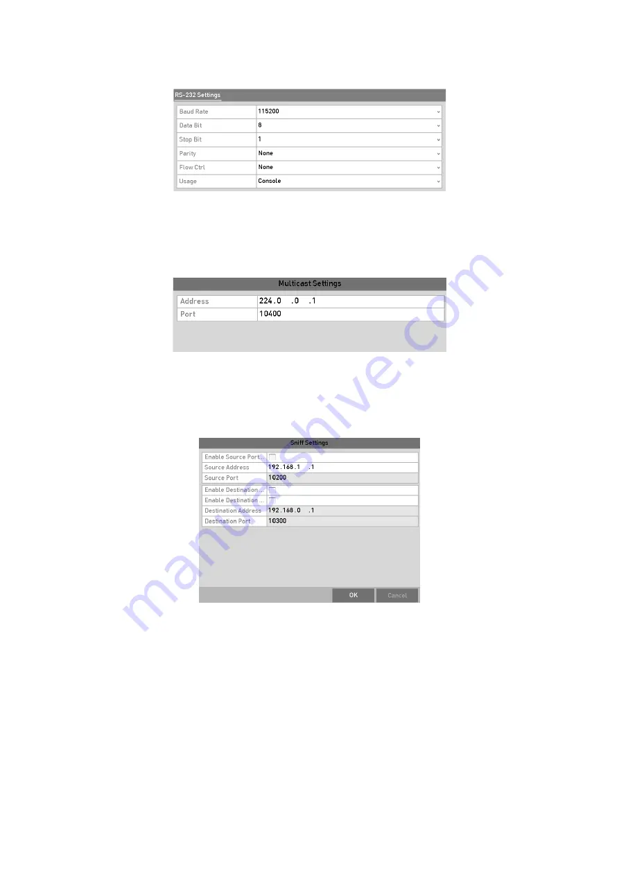
Multicast Connection


When connecting the DVR and the POS machine via Multicast protocol, set the 
multicast address and port.   


Multicast Settings 


Sniff Connection 

Connect the DVR and the POS machine via Sniff. Configure the source address 
and destination address settings.   


Sniff Settings 

Step


7

  Set other parameters of characters overly.   

4)

  Select the character encoding format from the drop-down list. 

5)

  Select the overlay mode of the characters to display in scrolling or page mode. 

6)

  Select the font size to small, medium or large.   

7)

  Set the overlay time of the characters. The value ranges from 5 to 3600 sec.   

8)

  Set the delay time of the characters. The value ranges from 5 to 3600 sec. 

9)

  (Optional) Check the checkbox to enable the

 POS Overlay in Live View

.  

10)

 Select the font color for the characters.   

Содержание GD-RT-5008P

Страница 1: ...______________________________________________________ User Guide Digital Video Recorders English ________________________________________________________________________________ UG GD RN xxxxxxx 2018...

Страница 2: ......

Страница 3: ...nfiguration with the Startup Wizard 34 2 5 Login and Logout 38 2 5 1 User Login 38 2 5 2 User Logout 39 2 6 Resetting Your Password 40 2 7 Adding and Connecting the IP Cameras 40 2 7 1 Activating the...

Страница 4: ...otion Detection Recording and Capture 78 5 4 Configuring the Alarm Triggered Recording and Capture 80 5 5 Configuring the Event Recording and Capture 81 5 6 Configuring the Manual Recording and Contin...

Страница 5: ...Detection 114 8 2 Setting Sensor Alarms 117 8 3 Detecting Video Loss 119 8 4 Detecting Video Tampering 120 8 5 Setting All day Video Quality Diagnostics 122 8 6 Handling Exceptions 123 8 7 Setting Ala...

Страница 6: ...figuring DDNS 154 12 2 3 Configuring the NTP Server 155 12 2 4 Configuring the NAT 156 12 2 5 Configuring More Settings 157 12 2 6 Configuring the HTTPS Port 159 12 2 7 Configuring Email 161 12 2 8 Ch...

Страница 7: ...ing the OSD Settings 187 15 2 Configuring a Privacy Mask 188 15 3 Configuring the Video Parameters 189 15 3 1 Configuring the Image Settings 189 15 3 2 Configuring the Camera Parameters Settings 191 1...

Страница 8: ...g User Accounts 203 17 5 1 Adding a User 203 17 5 2 Deleting a User 207 17 5 3 Editing a User 208 18 Important Notes 212 18 1 Glossary 212 18 2 Troubleshooting 213 18 3 List of Compatible Third Party...

Страница 9: ...duct model Further information about the product like Data Sheets CE Documents etc can also be found on the CD Rom in the product package This User Guide is a user manual for Digital Recorders DVRs Pl...

Страница 10: ...to 5 MP resolution of all the channels For GD RT AP5004P GD RT AP5008P GD RT AP5016N GD RT AT5016N 5 MP long distance transmission can be enabled for the analog cameras Independent configuration for...

Страница 11: ...module or the PoC module is powered off abnormally alarms are triggered and linkage methods are configurable GD RT AP5004P GD RT AP5008P GD RT AP5016N GD RT AT5016N support line crossing detection an...

Страница 12: ...or GD RT AT5016N 8 recording time periods with separated recording types Supports Channel Zero encoding Main stream and sub stream configurable for simultaneous recording Pre record and post record fo...

Страница 13: ...alarm notifying surveillance center sending email and alarm output One key disarms the linkage actions of the alarm input PTZ linking for the VCA alarm VCA detection alarm is supported Supports POS t...

Страница 14: ...rd files and downloading files broken transfer resume Remote parameters setup remote import export of device parameters Remote viewing of the device status system logs and alarm status Remote keyboard...

Страница 15: ...yboard and purple when IR remote and keyboard is used at the same time ALARM Turns red when a sensor alarm is detected HDD Flickers in red when data is being read from or written to HDD Tx Rx Flickers...

Страница 16: ...video output in live view or playback mode 3 DEF F2 Enters numeral 3 Enters letters DEF Uses the F2 button is used to change the tab pages Zooms in the image in PTZ control mode 4 GHI ESC Enters nume...

Страница 17: ...e 9 WXYZ PREV Enters numeral 9 Enters letters WXYZ Multi channel display in live view 0 A Enters numeral 0 Shifts the input methods in the editing text field Upper and lowercase alphabet symbols or nu...

Страница 18: ...itch in Auto switch mode 5 POWER Power on off switch 6 JOG SHUTTLE Control Moves the active selection up and down in a menu Cycles through different channels in live view mode Jumps 30s forward backwa...

Страница 19: ...om or written to HDD 3 Flashes white when the network is well connected 4 Receiver for IR remote control 5 USB Interface Universal Serial Bus USB ports for additional devices such as USB mouse and USB...

Страница 20: ...ription 1 POWER Power on off the device Power on off the device by pressing and holding the button for 5 seconds 2 MENU Button Press the button to return to the main menu after successful login Press...

Страница 21: ...tons can be used to cycle through channels In PTZ control mode it can control the movement of the PTZ camera ENTER Button Confirm selection in any of the menu modes It can also be used to tick checkbo...

Страница 22: ...ating the front control panel or the mouse Step 2 Check and remember the DVR No The default DVR No is 255 This number valid for all IR remote controls Step 3 Press the DEV button on the remote control...

Страница 23: ...se Control Name Action Description Left Click Single Click Live view Select channel and show the quick set menu Menu Select and enter Double Click Live view Switch between single screen and multi scre...

Страница 24: ...con Description Number English letter Lowercase Upperca se Backspace Switch the keyboard Space Positioning the cursor Enter Symbols Reserved 1 7 Rear Panel Note The rear panel vaires according to diff...

Страница 25: ...or VGA output Display local video output and menu 5 HDMI HDMI video output connector 6 USB Interface Universal Serial Bus USB port for additional devices 7 Network Interface Connector for network 8 RS...

Страница 26: ...l devices 5 HDMI1 VGA Simultaneous HDMI1 VGA output Display local video output and menu 6 HDMI2 HDMI2 video output connector 7 AUDIO OUT RCA connector 8 Network Interface Connector for network 9 RS 48...

Страница 27: ...Switch Switch for turning on off the device 12 GND Ground 13 LINE IN BNC connector for audio input 14 eSATA Connects external SATA HDD CD DVD RW 15 RS 232 Interface Connector for RS 232 devices 16 AL...

Страница 28: ...n electrical outlet It is HIGHLY recommended that an Uninterruptible Power Supply UPS be used in conjunction with the device Step 2 Turn on the power switch on the rear panel and the Power indicator L...

Страница 29: ...st three of the following categories upper case letters lower case letters numbers and special characters in order to increase the security of your product And we recommend you reset your password reg...

Страница 30: ...UID Step 5 After exporting GUID the Attention box pops up as below Click Yes to duplicate the password or No to cancel it 2 3 Using the Unlock Pattern for Login For the admin you can configure the unl...

Страница 31: ...een Release the mouse when the pattern is done Draw the Pattern Note Connect at least 4 dots to draw the pattern Each dot can be connected for once only Step 2 Draw the same pattern again to confirm i...

Страница 32: ...nlock Pattern Step 1 Right click the mouse on the screen and select the menu to enter the interface Draw the Unlock Pattern Step 2 Draw the pre defined pattern to unlock to enter the menu operation No...

Страница 33: ...33 If you have drawn the wrong pattern for 7 times the account will be locked for 1 minute Normal Login Dialog Box...

Страница 34: ...the language from the drop down list Step 2 Click Apply button Language Configuration Operating the Setup Wizard Step 1 The Start Wizard can walk you through some important settings of the device If y...

Страница 35: ...k Pattern for Login for reference 4 Optional Click of Export GUID to export GUID to the connected USB flash drive for resetting password Refer to Chapter 17 5 3 Editing a User for reference Step 3 Cli...

Страница 36: ...can enable DDNS and set other ports according to your need Set Advanced Network Parameters Step 7 For GD RT AT5016N click Next and you can enter the RAID configuration interface Check the checkbox of...

Страница 37: ...r inactive Before adding the camera make sure the IP camera to be added is in active status If the camera is in inactive status you can click the inactive icon of the camera to set the password to act...

Страница 38: ...terface Step 13 Click and you can enable the continuous recording or motion detection recording for all channels of the device Record Settings Step 14 Click OK to complete the wizard settings 2 5 Logi...

Страница 39: ...ou have entered the wrong password for 5 times the account will be locked for 60 seconds 2 5 2 User Logout After logging out the monitor turns to the live view mode and if you want to perform some ope...

Страница 40: ...eset Password Step 3 Input the new password and confirm the password Step 4 Click OK to save the new password Then the Attention box pops up as shown below Step 5 Click OK and the Attention box as bel...

Страница 41: ...face Step 2 Click the inactive icon of the camera to enter the following interface to activate it You can also select multiple cameras from the list and click the One touch Activate to activate the ca...

Страница 42: ...esetting the password monthly or weekly can better protect your product Step 4 Click OK to finish the acitavting of the IP camera And the security status of camera will be changed to Active 2 7 2 Addi...

Страница 43: ...ord from the list Note Make sure the camera to add has already been actiavted by setting the admin password and the admin password of the camera is the same with the DVR s Step 4 Optional Check the ch...

Страница 44: ...rotocol management port and other information of the IP camera to be added Note If the IP camera to add has not been actiavated you can activate it from the IP camera list on the IP Camera Management...

Страница 45: ...The camera is disconnected You can click the icon to get the exception information of camera Delete the IP camera Play the live video of the connected camera Advanced settings of the camera Upgrade t...

Страница 46: ...arameters Edit IP Camera Channel Port If the connected device is an encoding device with multiple channels you can choose the channel to connect by selecting the channel port No in the drop down list...

Страница 47: ...a to the DVR Step 1 Go to Menu Camera PoC Information Step 2 Check the status of connected PoC camera When the PoC camera is connected to the DVR the default status is AF If the connected PoC camera s...

Страница 48: ...nnected for the selected channel Step 3 Click Apply to save the settings Note You can view the max accessible number of IP cameras in the Max IP Camera Number text field For GD RT AT5016N disabling on...

Страница 49: ...n Alarm video loss tampering motion detection VCA or sensor alarm Record manual record schedule record motion detection or alarm triggered record Alarm Record Event Exception motion detection sensor a...

Страница 50: ...n output Auxiliary output For Live View Output Only 1 or HDMI2 VGA HDMI1 CVBS 2 or or HDMI2 CVBS VGA HDMI1 3 or VGA HDMI1 CVBS HDMI2 For other DVR with CVBS output the VGA HDMI output is the main outp...

Страница 51: ...enter the IP camera management interface For HDVR series only Playback Enter the playback interface and start playing back the video of the selected channel immediately PTZ Control A shortcut to enter...

Страница 52: ...ep 3 Select the Menu Output Mode to others from the right click menu on the monitor Step 4 On the pop up message box click Yes to reboot the device to enable the selected menu output as the main outpu...

Страница 53: ...oving the sliding bar You can also scroll the mouse wheel to control the zoom in out Image Settings icon can be selected to enter the Image Settings menu You can drag the mouse or click to adjust the...

Страница 54: ...you enable the function of one channel the other channels will disable the function automatically Both single window and multi window display modes support VCA information overlay Only the main output...

Страница 55: ...the remote client or web browser of 16 channels in one screen 3 4 Adjusting the Live View Settings Live View settings can be customized according to different needs You can configure the output interf...

Страница 56: ...the live view mode Volume Adjusts the volume of the audio output Event Output Designates the output to show event video If available you can select a different video output interface from the Video O...

Страница 57: ...ported for the VGA HDMI1 output 3 5 Manual Video Quality Diagnostics The video quality of the analog channels can be diagnosed manually and you can view the diagnostic results from a list Step 1 Go to...

Страница 58: ...58 Diagnostics Result Note Connect the camera to the device for the video quality diagnostics Three exception types can be diagnosed Blurred Image Abnormal Brightness and Color Cast...

Страница 59: ...rs for PTZ The configuring of the PTZ parameters should be done before you control the PTZ camera Step 1 Go to Menu Camera PTZ PTZ Settings Step 2 Select the camera for PTZ setting in the Camera drop...

Страница 60: ...rate data bit stop bit parity and flow control are not configurable Step 5 Optional Click Copy button to copy the settings to the other channels Select the channels you want to copy to and click OK to...

Страница 61: ...o 3 to save more presets You can click the Clear button to clear the location information of the preset or click the Clear All button to clear the location information of all the presets 4 2 2 Calling...

Страница 62: ...nnected Coaxitron camera dome Use the directional buttons on the PTZ control panel to operate the menu 4 2 3 Customizing Patrols Patrols can be set to move the PTZ to different key points and have it...

Страница 63: ...lick the Add button to add the next key point to the patrol or you can click the OK button to save the key point to the patrol You can delete all the key points by clicking the Clear button for the se...

Страница 64: ...be set by recording the movement of the PTZ You can call the pattern to make the PTZ movement according to the predefined path Step 1 Go to Menu Camera PTZ PTZ Settings Step 2 Choose pattern number in...

Страница 65: ...ect the PTZ option in the right click menu to show the PTZ control panel Step 2 Click the General tab to show the general settings of the PTZ control PTZ Panel General Step 3 Click the Call Pattern bu...

Страница 66: ...he left side of the right limit as well the angle from the left limit to the right limit should be no more than 180 4 2 8 Calling Linear Scan Follow the procedure to call the linear scan in the predef...

Страница 67: ...y after a period of inactivity park time Step 1 Click the button PTZ in the lower right corner of the PTZ Settings interface Or press the PTZ button on the front panel or click the PTZ Control icon in...

Страница 68: ...right corner which is next to the Back button OPTION 2 In the Live View mode you can press the PTZ Control button on the front panel or on the remote control or choose the PTZ Control icon in the qui...

Страница 69: ...n button and the auto cycle button Zoom Focus Iris Zoom Focus Iris The speed of the PTZ movement Light on off Wiper on off 3D Zoom Image Centralization Menu Switch to the PTZ control interface Switch...

Страница 70: ...ease install a HDD and initialize it Menu HDD General HDD General Step 2 Click Advanced tab to check the storage mode of the HDD Menu HDD Advanced Storage Mode 1 If the HDD mode is Quota please set th...

Страница 71: ...owing parameters for the Main Stream Continuous and the Main Stream Event Stream Type Set the stream type to be Video or Video Audio Resolution Set recording resolution Note GD RT AP5004P GD RT AP5008...

Страница 72: ...RT AP5016N GD RT AT5016N when 5 MP signal input is connected the frame rate of the main stream cannot exceed 12 fps When 4 MP signal input is connected the frame rate of the main stream cannot exceed...

Страница 73: ...9 59 55 Post record The time you set to record after the event or the scheduled time For example when an alarm triggered the recording ends at 11 00 if you set the post record time as 5 seconds it re...

Страница 74: ...Copy to copy the settings to other analog channels if needed Copy Camera Settings Step 7 Set encoding parameters for sub stream 1 Select the Sub Stream tab Sub Stream Encoding 2 Select a camera in th...

Страница 75: ...o other cameras click Copy to copy the settings to other channels Note The interval is the time period between two capturing actions You can configure all the parameters on this menu on your demand 5...

Страница 76: ...alarm M A recording triggered by motion detection and alarm POS recording triggered by POS and alarm Note The POS recording is supported by GD RT AT5016N only Step 2 Choose the camera you want to conf...

Страница 77: ...h each other To enable Event Motion Alarm M A motion or alarm M A motion and alarm and POS triggered recording you must configure the motion detection settings alarm input settings or VCA settings as...

Страница 78: ...4 to set schedule for other channels If the settings can also be used to other channels click Copy and then choose the channel to which you want to copy to Step 5 Click Apply in the Record Schedule i...

Страница 79: ...ox after Enable Motion Detection 3 Drag and draw the area for motion detection by mouse If you want to set the motion detection for all the area shot by the camera click Full Screen To clear the motio...

Страница 80: ...e refer to the step 4 of Chapter 5 2 Configuring the Recording and Capture Schedule while you may choose Motion as the record type 5 4 Configuring the Alarm Triggered Recording and Capture Follow the...

Страница 81: ...e the settings Repeat the steps from 1 to 8 to configure other alarm input parameters If the settings can also be applied to other alarm inputs click Copy and choose the alarm input number Copy Alarm...

Страница 82: ...RT AC3016N also support 1 ch sudden scene change detection Channels with audio support audio exception detection For the analog channels the line crossing detection and intrusion detection conflict w...

Страница 83: ...the Manual Recording and Continous Capture Follow the steps to set parameters for the manual recording and continuous capture Using manual recording and continuous capture you need to manually cancel...

Страница 84: ...rd of all channels Note After rebooting all the manual records enabled are canceled 5 7 Configuring the Holiday Recording and Capture Follow the steps to configure the record or capture schedule on ho...

Страница 85: ...uring Recording and Capture Schedule while you may choose Holiday in the Schedule drop down list or you can draw the schedule on the timeline of Holiday Note Up to 8 periods can be configured for each...

Страница 86: ...ings to Group before you set the HDD property to Redundant For detailed information please refer to Chapter 14 3 Managing HDD Group There should be at least another HDD which is in Read Write status S...

Страница 87: ...1 Go to Menu HDD Advanced Storage Mode Check whether the storage mode of the HDD is Group If not set it to Group For detailed information please refer to Chapter 14 3 Managing HDD Group Step 2 Select...

Страница 88: ...gs Note After you have configured the HDD groups you can configure the recording settings following the procedure provided in Chapter 5 2 5 7 5 10 Files Protection You can lock the recorded files or s...

Страница 89: ...then click the icon which will turn to indicating that the file is locked Note The record files of which the recording is still not completed cannot be locked 2 Click to change it to to unlock the fi...

Страница 90: ...o Read only the DVR cannot record any files Only live view mode is available If you set the HDD to Read only when the DVR is saving files in it then the file will be saved in next R W HDD If there is...

Страница 91: ...on and reboot the device to have new settings taken effect Task 2 One Key Disabling H 264 H 265 for All Analog Cameras Step 1 Go to Menu Record Advanced Step 2 Click Disable to disable H 264 for all t...

Страница 92: ...e checkbox of 1080P Lite Mode and click Apply to pop up the attention box After enabling 1080p lite mode the 3 MP signal is not accessible to analog channel Step 3 Click Yes to reboot the device to ha...

Страница 93: ...el in live view mode and click the button in the quick setting toolbar Note In the instant playback mode only record files recorded during the last five minutes on this channel will be played back Ins...

Страница 94: ...nnel list and then double click to select a date on the calendar Playback Calendar Note If there are record files for that camera in that day in the calendar the icon for that day is displayed as Othe...

Страница 95: ...ck of multiple channels Toolbar of Playback Detailed Explanation of Playback Toolbar Button Operation Button Operation Button Operation Audio on Mute Start Stop clipping Lock File Add default tag Add...

Страница 96: ...any point of the progress bar to locate special frames The POS overlay function is supported by GD RT AT5016N only When the POS is enabled when playing back the POS information will be overlaid on the...

Страница 97: ...maximum number of channels for synchronous playback supported varies to different models Step 6 On the Event Playback interface you can select the main stream or sub stream from the drop down list fo...

Страница 98: ...g s to search for record files and position time point Before playing back by tag Step 1 Go to Menu Playback Step 2 Search and play back the record file s Refer to Chapter 6 1 2 Playing Back by Normal...

Страница 99: ...s or next tag Please refer to Table 6 1 for the description of buttons on the toolbar 6 1 5 Playing Back by Smart Search The smart playback function provides an easy way to get through the less effect...

Страница 100: ...e methods Refer to the user manual of smart IP camera for detailed instructions Steps Step 1 Go to Menu Playback Step 2 Select the Smart in the drop down list on the top left side Step 3 Select a came...

Страница 101: ...Detection Click the button and specify 4 points to set a quadrilateral region for intrusion detection Only one region can be set Motion Detection Click the button and then click and draw the mouse to...

Страница 102: ...be shown on the playback interface Click to hide the VCA information Note This function is supported by GD RT AP5004P GD RT AP5008P GD RT AP5016N GD RT AT5016N In smart playback both the analog and I...

Страница 103: ...arch Step 3 Choose a log with record file and click button to enter Playback interface Note If there is no record file at the time point of the log the message box No result found will pop up Step 4 P...

Страница 104: ...pper left corner of the page to enter the Sub periods Playback interface Step 3 Select a date and start playing the video file Step 4 Select the Split screen Number from the drop down list Up to 16 sc...

Страница 105: ...down list on the top left side The files are listed in the right side list You can click the button to refresh the file list Step 3 Select and click the button to play back it Interface of External Fi...

Страница 106: ...hoose a picture you want to view and click button You can click Back to return to the search interface Result of Picture Playback Step 6 The toolbar in the bottom part of Playback interface can be use...

Страница 107: ...m Step 1 Click the button on the playback control bar to enter Digital Zoom interface Step 2 You can zoom in the image to different proportions 1 to16X by moving the sliding bar from to You can also s...

Страница 108: ...Step 1 Enter the playback interface Step 2 Click on the toolbar to enter the file management interface File Management Step 3 You can view the saved video clips captured playback pictures lock unlock...

Страница 109: ...g USB flash drives and USB HDDs Step 1 Go to Menu Export Normal Picture Step 2 Select the cameras to search Step 3 Set search condition and click Search button to enter the search result interface Nor...

Страница 110: ...terface Export by Normal Video Search using USB Flash Drive Step 6 Select the backup device from the drop down list and you can also select the file format to filter the files existing in the backup d...

Страница 111: ...ng USB devices USB flash drives USB HDDs USB writer SATA writer or eSATA HDD Quick Backup and Normal Backup are supported Step 1 Go to Menu Export Event Step 2 Select the cameras to search Step 3 Sele...

Страница 112: ...o Clips You may also select video clips in playback mode to export directly during Playback using USB devices USB flash drives USB HDDs USB writer or SATA writer Step 1 Go to Menu Playback Step 2 Duri...

Страница 113: ...Management Step 2 Backup device management Click New Folder button if you want to create a new folder in the backup device Select a record file or folder in the backup device and click button if you w...

Страница 114: ...want to set up motion detection Step 3 Set detection area and sensitivity Check checkbox to enable motion detection Use the mouse to draw detection area s or click Full Screen to set the detection are...

Страница 115: ...s arming schedule Choose one day of a week and up to eight time periods can be set within each day Or you can click the Copy button to copy the time period settings to other day s Note Time periods sh...

Страница 116: ...ete the motion detection settings of the channel Step 7 If you want to set motion detection for another channel repeat the above steps or just copy the above settings to it Note You are not allowed to...

Страница 117: ...arm Input Step 3 Select Trigger Channel tab and select one or more channels which will start to record or become full screen monitoring when an external alarm input is triggered Step 4 Select Arming S...

Страница 118: ...arm input Note Check whether the PTZ or speed dome supports PTZ linkage One alarm input can trigger presets patrol or pattern of more than one channel But presets patrols and patterns are exclusive Se...

Страница 119: ...ttings are not configurable 8 3 Detecting Video Loss Detect video loss of a channel and take alarm response action s Step 1 Go to Menu Camera Video Loss Video Loss Setup Interface Step 2 Select a Came...

Страница 120: ...n tab to set up alarm response action of video loss please refer to Chapter 8 7 Setting Alarm Response Actions Step 6 Click the OK button to complete the video loss settings of the channel Repeat the...

Страница 121: ...el 1 Click Arming Schedule tab to set the arming schedule of response action 2 Select one day of a week and up to eight time periods can be set within each day Note Time periods shall not be repeated...

Страница 122: ...ng steps to set the threshold of the diagnosing and the linkage actions Step 1 Go to Menu Camera Video Quality Diagnostics Video Quality Diagnostics Interface Step 2 Select a Camera you want to detect...

Страница 123: ...stics 3 Select Linkage Action tab to set alarm response actions of video quality diagnostics alarm please refer to Chapter 8 7 Setting Alarm Response Actions Repeat the above steps to set arming sched...

Страница 124: ...resolution Record Capture Exception No space for saving recorded files or captured pictures PoC Module Exception The DVR cannot detect the PoC module or the PoC module is powered off abnormally Step 1...

Страница 125: ...Audible Warning buzzer Notify Surveillance Center Send Email and Trigger Alarm Output Full Screen Monitoring When an alarm is triggered the local monitor HDMI VGA or CVBS monitor displays in full scre...

Страница 126: ...ut when an alarm is triggered Step 1 Go to Menu Configuration Alarm Alarm Output Step 2 Select an alarm output and set alarm name and dwell time Alarm Output Settings Interface Note If Manually Clear...

Страница 127: ...ation POS POS Settings Step 2 Select the POS from the drop down list Up to 8 POS units are selectable Step 3 Check the checkbox to enable the POS function POS Settings Step 4 Filter the POS privacy in...

Страница 128: ...to take the new settings into effect 1 Click Set button to enter the NUCLEUS Settings interface 2 Edit the Employee Shift and Terminal information No more than 32 characters can be input 3 Click OK t...

Страница 129: ...to RS 232 convertor including the serial number of port baud rate data bit stop bit parity and flow ctrl Note When using USB RS 232 convertor mode the port of USB to RS 232 convertor and the POS must...

Страница 130: ...ep 7 Set other parameters of characters overly 4 Select the character encoding format from the drop down list 5 Select the overlay mode of the characters to display in scrolling or page mode 6 Select...

Страница 131: ...py the current settings to other POS s Copy POS Settings 9 2 Configuring the Overlay Channel You can assign the POS machine to corresponding channel on which you want to overlay Step 1 Go to Menu Conf...

Страница 132: ...9 3 Configuring the POS Alarm Set the POS alarm parameters to trigger certain channels to start recording or trigger full screen monitoring audio warning notifying the surveillance center sending ema...

Страница 133: ...ngs to other day s Note Time periods shall not be repeated or overlapped Set Arming Schedule Step 6 Click the Handling tab to set up alarm response actions of POS alarm Refer to Chapter 8 7 Setting Al...

Страница 134: ...134 Set PTZ Linking Step 8 Click OK to save the settings...

Страница 135: ...GD RT AC3004N and GD RT AC3016N series support 4 ch line crossing detection and intrusion detection GD RT AC3016N series also support 1 ch sudden scene change detection Channels with audio support au...

Страница 136: ...linking for the face detection alarm Please refer to step 3 to step 5 of Chapter 8 2 Setting Sensor Alarms for detailed instructions PTZ Linking Step 5 Click the Rule Settings button to set the face d...

Страница 137: ...ming schedule linkage action and PTZ linking Note The PTZ linking is only applicable to other list not to whitelist and blacklist Step 6 Click the Rule Settings to enter the rule settings interface Co...

Страница 138: ...object goes across the configured line both directions can be detected and alarms are triggered A B Only the object crossing the configured line from the A side to the B side can be detected B A Only...

Страница 139: ...tions can be taken when the alarm is triggered Step 1 Go to Menu Camera VCA Step 2 Select the camera to configure the VCA You can check the checkbox of Save VCA Picture to save the captured pictures o...

Страница 140: ...Range 1 100 Percentage defines the ratio of the in region part of the object which can trigger the alarm For example if the percentage is set as 50 when the object enters the region and occupies half...

Страница 141: ...when the alarm is triggered Step 1 Go to Menu Camera VCA Step 2 Select the camera to configure the VCA You can check the checkbox of Save VCA Picture to save the captured pictures of VCA detection St...

Страница 142: ...Region Entrance Detection for operating steps to configure the region exiting detection Up to 4 rules can be configured 10 7 Loitering Detection This function may not be available in each recorder mo...

Страница 143: ...lable in each recorder model Fast moving detection alarm is triggered when people vehicle or other objects move fast in a pre defined virtual region and a series of actions can be taken when the alarm...

Страница 144: ...in the region for 10s And the Sensitivity defines the similarity degree of the background image Usually when the sensitivity is high a very small object left in the region can trigger the alarm Up to...

Страница 145: ...pictures of VCA detection Step 3 Select the VCA detection type to Audio Exception Detection Step 4 Click to configure the trigger channel arming schedule linkage action and PTZ linking for the audio...

Страница 146: ...er the alarm 10 15 Sudden Scene Change This function may not be available in each recorder model Scene change detection function detects the change of surveillance environment affected by the external...

Страница 147: ...tep 1 Go to Menu Camera VCA Step 2 Select the camera to configure the VCA You can check the checkbox of Save VCA Picture to save the captured pictures of VCA detection Step 3 Select the VCA detection...

Страница 148: ...tured face pictures or video files Step 4 Upload the pictures from your local storage device for matching the detected face pictures Step 5 Set the similarity level for the source pictures and the cap...

Страница 149: ...aggage detection object removal detection region entrance detection region exiting detection parking detection loitering detection people gathering detection and fast moving detection Step 5 Click Sea...

Страница 150: ...ep 6 Click Search to start searching The search results of detected vehicle plate pictures are displayed in list or in chart Note Please refer to the Step 7 to Step 8 of Chapter 10 1 Face Search for t...

Страница 151: ...at map processing Step 3 Select the report type to Daily Report Weekly Report Monthly Report or Annual Report Step 4 Set the statistics time Step 5 Click the Counting button to export the report data...

Страница 152: ...T5016N and it allows the device to work in Multi address and Net fault Tolerance Multi address Mode The parameters of the two NIC cards can be configured independently You can select LAN1 or LAN2 in t...

Страница 153: ...12 2 1 Configuring the PPPoE Settings The DVR also allows access by Point to Point Protocol over Ethernet PPPoE Step 1 Go to Menu Configuration Network PPPoE PPPoE Settings Interface Step 2 Check the...

Страница 154: ...tep 3 Select DDNS Type Three different DDNS types are selectable DynDNS PeanutHull and NO IP DynDNS 1 Enter Server Address for DynDNS i e members dyndns org 2 In the Device Domain Name text field ente...

Страница 155: ...enable this feature Step 3 Configure the following NTP settings Interval Time interval between the two synchronizing actions with NTP server The unit is minute NTP Server IP address of NTP server NTP...

Страница 156: ...he router to which your device is connected When the network working mode of the device is set as multi address the Default Route of the device should be in the same network segment as that of the LAN...

Страница 157: ...l requirements External Port indicates the port No for port mapping in the router The value of the RTSP port No should be 554 or between 1024 and 65535 while the value of the other ports should be bet...

Страница 158: ...more than the maximum number of cameras through network A multicast address spans the Class D IP range of 224 0 0 0 to 239 255 255 255 It is recommended to use the IP address ranging from 239 252 0 0...

Страница 159: ...web site and associated web server that one is communicating with which protects against Man in the middle attacks Perform the following steps to set the port number of https Example If you set the po...

Страница 160: ...lick OK to save the settings OPTION 2 Create the authorized certificate 1 Click the Create button to create the certificate request 2 Download the certificate request and submit it to the trusted cert...

Страница 161: ...intains an SMTP mail server The network must also be connected to either an intranet or the Internet depending on the location of the e mail accounts to which you want to send notification Additional...

Страница 162: ...f the Email Receiver s Address The Email address of the receiver Enable Attached Picture Check the checkbox if you want to send email with attached alarm images The interval is the time between two ca...

Страница 163: ...erface Step 2 You can view the sending rate and receiving rate information on the interface The traffic data is refreshed every 1 second 12 3 Configuring the Network Detection You can obtain network c...

Страница 164: ...Maintenance Net Detect Network Detection Step 2 Select the backup device from the drop down list of Device Name Note Click the Refresh button if the connected local backup device cannot be displayed W...

Страница 165: ...Detection Step 2 Click Status on the right bottom of the interface Checking Network Status If the network is normal the following message box pops out Network Status Checking Result If the message bo...

Страница 166: ...stics to obtain the real time information of the device Step 1 Go to Menu Maintenance Net Detect Network Stat Network Stat Interface Step 2 View the bandwidth of Remote Live View bandwidth of Remote P...

Страница 167: ...oftware You can enable the RAID function on your demand Note The GD RT AT5016N supports the RAID0 RAID1 RAID5 RAID6 and RAID 10 array types Before you start Please install the HDD s properly and it is...

Страница 168: ...ction in the Wizard when the device startup please refer to step 7 of Chapter 2 3 2 OPTION 2 Enable the RAID function in the HDD Management Interface Step 1 Enter the Disk Mode configuration interface...

Страница 169: ...interface Step 4 Edit the array name in the Array Name text filed and click OK button to start configuring array Note If you install 4 HDDs or above for one touch configuration a hot spare disk will...

Страница 170: ...lect is not compatible with the requirement of the RAID level the error message box will pop up Step 5 You can click Array tab to view the successfully created array 13 2 Rebuilding Array The working...

Страница 171: ...a hot spare disk to ensure the high security and reliability of the array 13 2 2 Manually Rebuilding Array If the hot spare disk has not been configured you can rebuild the array manually to restore...

Страница 172: ...Note Deleting array will cause to delete all the data in the array 13 4 Checking and Editing the Firmware You can view the information of the firmware and set the background task speed on the Firmwar...

Страница 173: ...ed Step 3 Click the Init button Confirm Initialization Step 4 Select the OK button to start initialization Step 5 After the HDD has been initialized the status of the HDD will change from Uninitialize...

Страница 174: ...he HDDs will be set to work for all time 14 2 Managing a Network HDD You can add the allocated NAS or disk of IP SAN to DVR and use it as network HDD Step 1 Go to Menu HDD General HDD Information Inte...

Страница 175: ...st manually enter the directory in the text field of NetHDD Directory 4 Click OK to add the configured NAS disk Note Up to 8 NAS disks can be added Add NAS Disk Add IP SAN 1 Enter the NetHDD IP addres...

Страница 176: ...ed NetHDD is uninitialized please select it and click the Init button for initialization Initialize Added NetHDD 14 3 Managing a HDD Group 14 3 1 Setting HDD Groups Multiple HDDs can be managed in gro...

Страница 177: ...l pop up Attention for Reboot Step 4 Click the Yes button to reboot the device to activate the changes Step 5 After reboot of device go to Menu HDD General Step 6 Select HDD from the list and click th...

Страница 178: ...ode to Group refer to step1 4 of Chapter 14 3 1 Setting HDD Groups A HDD can be set to read only to prevent important recorded files from being overwritten when the HDD becomes full in overwrite recor...

Страница 179: ...d with allocated quota for the storage of recorded files Steps Step 1 Go to Menu HDD Advanced Storage Mode Step 2 Set the Mode to Quota as shown below Note The DVR must be rebooted to enable the chang...

Страница 180: ...to apply the settings Note If the quota capacity is set to 0 then all cameras will use the total capacity of HDD for record 14 5 Configuring a Cloud Storage The cloud storage facilitates you to uploa...

Страница 181: ...p 6 Enter the cloud storage interface again about 20s later When the Status shows online it indicates the successful registration Step 7 Configure the recording schedule Back to enter the record inter...

Страница 182: ...rresponding event type Step 9 Optional You can click the Copy button to copy the cloud storage settings to other cameras You can also click the checkbox of Analog IP Camera to select all cameras Click...

Страница 183: ...e as that of the clone source disk Step 4 Check the checkbox of the HDD to be cloned in the Clone Source list Step 5 Click the Clone button and a message box pops up Step 6 Click the Yes button to con...

Страница 184: ...t as shown below View HDD Status 2 14 8 Checking the S M A R T Information The S M A R T Self Monitoring Analysis and Reporting Technology is a monitoring system for HDD to detect and report on variou...

Страница 185: ...HDD to check the status of the HDD Step 1 Go to Menu Maintenance HDD Detect Bad Sector Detection Step 2 Select a HDD and click the Detect button to start detecting Bad Sector Detecting Step 3 You can...

Страница 186: ...2 Select the Exception Type to HDD Error from the drop down list Step 3 Check the checkbox s below to select the linkage action s for HDD error as shown in Figure 12 26 The linkage actions can be sele...

Страница 187: ...ext field Step 4 Configure the Display Name Display Date and Display Week by checking the checkbox Step 5 Select the Date Format Time Format Display Mode and the OSD Font OSD Configuration Interface S...

Страница 188: ...ck to the OSD Configuration interface Step 8 Click the Apply button to apply the settings 15 2 Configuring a Privacy Mask You are allowed to configure the four sided privacy mask zones that cannot be...

Страница 189: ...the corresponding Clear Zone1 4 icons on the right side of the window or click Clear All to clear all zones Set Privacy Mask Area Step 6 You can click the Copy button to copy the privacy mask settings...

Страница 190: ...rlapped with each other Step 4 Select the mode from the drop down list of Mode there are four modes selectable for the analog cameras Standard Indoor Dim Light and Outdoor Step 5 Adjust the image para...

Страница 191: ...al Click Default to set the parameters to the default settings Step 5 Optional Click Copy to copy the parameters of the current camera to other analog cameras Step 6 Click Apply to save the settings N...

Страница 192: ...Files The operation alarm exception and information of the DVR can be stored in log files which can be viewed and exported at any time Step 1 Go to Menu Maintenance Log Information Step 2 Set the log...

Страница 193: ...you want to export the log files click the Export button to enter the Export menu as shown below Export Log Files Step 7 Select the backup device from the drop down list of Device Name Step 8 Click t...

Страница 194: ...etting to other devices by importing the excel file to it Step 1 Go to Menu Camera Camera IP Camera Import Export Step 2 Click the Export button to export configuration files to the selected local bac...

Страница 195: ...fter the import process is completed you must reboot the DVR After having finished the import of configuration files the device will reboot automatically 16 5 Upgrading the System The firmware on your...

Страница 196: ...After the upgrading is completed reboot the DVR to activate the new firmware 16 5 2 Upgrading by FTP Before you start Configure PC running FTP server and DVR to the same Local Area Network Run the 3r...

Страница 197: ...rade button to start upgrading Step 4 After the upgrading is completed reboot the DVR to activate the new firmware 16 6 Upgrading the Camera You can upgrade multiple connected analog cameras supportin...

Страница 198: ...ra s for upgrading Note The analog camera must support HD TVI or AHD signal Step 3 Select the update file from the backup device Step 4 Click the Upgrade button to start upgrading 16 7 Restoring Defau...

Страница 199: ...working mode default route server port etc and user account parameters to the factory default settings Factory Defaults Restore all parameters to the factory default settings Restore to Inactive Resto...

Страница 200: ...used is English Output Standard Select the output standard to be PAL or NTSC VGA HDMI Resolution Select the output resolution which must be the same with the resolution of the VGA HDMI display Note F...

Страница 201: ...2 Configuring the RS 232 Serial Port Note The RS 232 serial port is supported by GD RT AT5016N The RS 232 port can be used in two ways Parameters Configuration Connect a PC to the DVR through the PC s...

Страница 202: ...Device Name Edit the name of DVR Device No Edit the serial number of DVR The Device No can be set in the range of 1 to 255 and the default No is 255 Auto Logout Set timeout time for menu inactivity E...

Страница 203: ...pops up 3 Click Yes to apply the function and reboot the device Note If you have configured 2K 4K output or connected 4 MP 5 MP signal input already when you enable enhanced VCA mode and after the de...

Страница 204: ...STRONG PASSWORD RECOMMENDED We highly recommend you create a strong password of your own choosing Using a minimum of 8 characters including at least three of the following categories upper case lette...

Страница 205: ...in the Camera Configuration by default User s MAC Address The MAC address of the remote PC which logs onto the DVR If it is configured and enabled it only allows the remote user with this MAC address...

Страница 206: ...d by HDVR series Local Advanced Operation Operating HDD management initializing HDD setting HDD property upgrading system firmware Local Shutdown Reboot Shutting down or rebooting the device Remote Co...

Страница 207: ...alarm output of the selected camera s Remote Manual Operation Remotely starting stopping manual recording picture capturing and alarm output of the selected camera s Local Playback Locally playing bac...

Страница 208: ...unt 17 5 3 Editing a User For the added user accounts you can edit the parameters Step 1 Go to Menu Configuration User Step 2 Select the user to be edited from the list Step 3 Click the icon to enter...

Страница 209: ...8 characters including at least three of the following categories upper case letters lower case letters numbers and special characters in order to increase the security of your product And we recommen...

Страница 210: ...ck Pattern to modify the pattern Step 7 Optional Click icon after Export GUID to pop up the Reset Password interface Click Export button to export GUID to the USB flash drive for retrieving the forgot...

Страница 211: ...of the admin before exporting GUID Step 8 Click the OK button to save the settings and exit from the menu Step 9 Optional For the Operator or Guest user account you can also click the button on the U...

Страница 212: ...Point to Point Protocol over Ethernet is a network protocol for encapsulating Point to Point Protocol PPP frames inside Ethernet frames It is used mainly with ADSL services where individual users conn...

Страница 213: ...ion cable is good If there is still no image display on the monitor after rebooting please check if the connection cable is good and change a cable to connect again Step 3 Verify Input mode of the mon...

Страница 214: ...te Step 1 Check the parameters of Main Stream Continuous and Main Stream Event Select Menu Record Parameters Record and set the resolution of Main Stream Event the same as the one of Main Stream Conti...

Страница 215: ...wer level Step 3 Reduce the number of local playback channel Select Menu Playback and uncheck the checkbox of unnecessary channels Step 4 Check if the fault is solved by the above steps If it is solve...

Страница 216: ...24 1 7 00 1280 720 Samsung SND 5 080P 3 10_130416 1280 1024 Vivotek FD813 4 0107a 1280 800 Bosch Dinion NBN 9 21 P V10500453 1280 720 Panasonic SP306 H Application 1 34 Image Data 1 06 1280 960 Cannon...

Отзывы: