background image

57

GROWSPAN

 GOTHIC PREMIUM HIGH TUNNELS

Revision date: 01.08.21    108179_80_81_82_83_84H

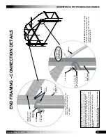
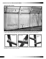
END FRAMING - CONNECTION DET

AILS

106755

1/2"

Bolt

&W

as

he

r

1/2"

x5

1/2"

Bolt

Assemb

ly

Guid

eP

os

t

Customer

This

Side

Te

kS

cr

ew

s

Screws

Wood

4"

x4

"

Su

pp

lied

By

107923

3/8"

Thre

aded

Ro

d

Guid

eP

os

t

Rafter

To

Be

Cu

tI

nF

ield

(2

)3

/8

"N

ut

sa

nd

Wash

er

4"

x4

"

Su

pp

lied

By

Customer

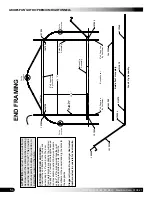
ATTENTION:

 Panel is not shown. Sink 

threaded rod below the surface of the  customer-supplied end wall post. See  details on page 18.

Threaded rod and rafter are not  shown. Roll-up door panel is  not shown.

104188B 1/2" bolt,  FALB08B nut, &  FAME09B washer

FAK16 ROD (cut), FALB04B nuts &  FAME08B washer

CUST

OMER-SUPPLIED END FRAME: 

Construct the end 

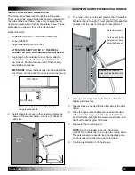
frame for the roll-up end panel using 4" x 4" wood posts.  The doorframe materials are supplied by the customer

If quality 4" x 4" lumber at the lengths needed is not  available, construct 2-ply wood beams using 2" x 6" boards  secured together with exterior grade bolts and nuts. Center  the doorframe in the end wall and dig the holes for the  doorjambs.


Stagger all joints. Do not align.


Use treated lumber and 

set in concrete for best results.


Содержание Gothic Premium 108179H

Страница 1: ...you are completing the correct steps for your building The cover installation steps for buildings with a film cover or a 5 2 oz fabric cover are the same STK DIMENSIONS 108179H 20 W x 14 H x 24 L 1081...

Страница 2: ...mage LOCATION Choosing the proper location is an important step before you begin to assemble the structure Follow these requirements Never erect the structure under power lines Identify whether underg...

Страница 3: ...ts to the main frame install the panel and attach the anti billow ropes 14 Read the care and maintenance information at the end of these instructions 15 Complete and return all warranty information as...

Страница 4: ...Customer Supplied End Framing Installation In areas where loose or sandy soil conditions are found or where deep frost is common setting the customer supplied end frame posts in concrete is recommend...

Страница 5: ...with the next A customer supplied two piece ribbon board is required for the drop down panel Fasteners are included Customer supplies the materials for the ribbon board Minimum board requirements are...

Страница 6: ...oose in sandy soil when concrete is not used Minimum board requirements are shown in the diagrams below If a ribbon board is not used attach the 104211 double u channel directly to the rafters along t...

Страница 7: ...bulk material used to cover the open areas of the end frame and door frame See End Panel Location diagram in the Quick Start section of this guide DD084HxxxCN52 This number identifies the panels used...

Страница 8: ...ons describe the installation of the optional ridge vent kit Additional purchase required The ridge vent kit is designed for use with the HF model 5 2 oz cover only If you have the C model or did not...

Страница 9: ...the same step for the last corner post NOTE The distance measured diagonally between corner posts must be equal for the building to be square 7 Check all dimensions and adjust if needed before driving...

Страница 10: ...and arrange on a level surface 2 Slide one 1 end purlin clamp 102856 onto the peak rafter pipe and one clamp onto each leg pipe Position end clamps on the rafter pipes as shown 3 Insert the swaged end...

Страница 11: ...t Depending on the frame size a lift and additional assistants may be needed Consult Quick Start section for details Rafter shown differs in design ATTENTION Stand the rafter so the end clamp nuts and...

Страница 12: ...in position DO NOT USE THE REMAINING END RAFTER ATTENTION Do not add a band clamp A band clamp is only added to the end rafters and the first interior rafters at either end of the frame 13 Secure the...

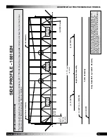
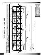
Страница 13: ...ipes 3 Using the diagram below and the Side Profile diagram in the Quick Start section as guides position a purlin diagonally and secure to each rafter it crosses using pipe straps and Tek screws NOTE...

Страница 14: ...red for drop down sides Position strut so it will not interfere with the installation of the baseboard Ground Level 2 Attach one end of the strut to the band clamp as shown in the diagram below Strut...

Страница 15: ...the boards Customer supplies baseboard material Minimum lumber dimension is 2 x 6 Use treated lumber if allowed by local codes for your application Always check codes before purchasing treated lumber...

Страница 16: ...ts were driven into place and not set in concrete read the information on this page and anchor the high tunnel before continuing Ground Level Ground post below grade Anchor Kit Components Ground post...

Страница 17: ...OOR HEIGHT GROUND TO BOTTOM OF HEADER 116673 ENDWALL HEADER KIT 20 WIDE GOTHIC PREMIUM HIGH TUNNEL additional purchase required If the 116673 endwall header kit was purchased for this high tunnel cons...

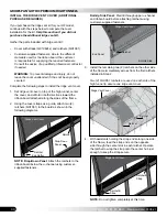
Страница 18: ...NOTE Use recognized construction practices when setting the customer supplied 4 x 4 posts 2 After setting the posts install the header Consult the End Framing Connections Details diagram in the Quick...

Страница 19: ...Use DCC4931 Material Consult the End Panel Location diagram near the back of this manual to view the areas that need to be covered with end panel material Use these steps to cut and attach the end pan...

Страница 20: ...ing side 4 Inspect the frame assembly for sharp edges or clamps and bolts that may interfere with the installation of the side panels File or tape sharp edges as needed Reposition clamps if needed 5 C...

Страница 21: ...screw in each channel and into each rafter See the diagram that follows 2 Continue attaching the u channel sections to the ribbon board or rafters for no ribbon board and work toward the other end of...

Страница 22: ...NGTH OF HIGH TUNNEL Raw 5 2 oz Cover Material End of the cover positioned at the end of the frame Position ridge vent holes here at each end Center Line RIDGE VENT KIT INSTRUCTIONS The optional Ridge...

Страница 23: ...to the template as shown above Space the three 3 holes 9 on center 9 24 12 3 VENT HOLE TEMPLATE Center Line Length Cover Cover Width 3 0 Step 2 Step 1 9 9 3 3 Edge of Cover Center Line Cover 9 9 3 Ste...

Страница 24: ...easurements to ensure you are pulling the cover onto the frame correctly Complete these steps 1 Take the cover and position it at the frame base along one side NOTE Unfold cover and locate edge Cover...

Страница 25: ...PROTECTION WHEN INSTALLING SPRING WIRE Step 3 Step 5 7 4 Center side to side and end to end 5 Once main cover is in place and centered begin at the peak at one end and install the 102198A wire spring...

Страница 26: ...FOR DROP DOWN SIDES all CD FD models CONTINUE WITH THE INSTALL THE DROP DOWN SIDES PROCEDURE FOR ROLL UP SIDES all CRU FRU models CONTINUE WITH THE INSTALL THE ROLL UP SIDES PROCEDURE 8 Move to the o...

Страница 27: ...pe assembly See side profile for pipe identification if needed 106734 band clamp 103496 gearbox and 103544 mounting plate 102717 double drive FA4482B Tek screws for drive pipe FAH009B 1 4 x 4 carriage...

Страница 28: ...ed to the end rafter take the 103496 gearbox and place it against the mounting plate at the desired angle 6 Using a marker trace the edges of the gearbox to mark the desired angle on the mounting plat...

Страница 29: ...of the second rafter using an FA4482B Tek screw Pipe should remain loose in the band clamp Band clamps support the drive pipe at each rafter except the end rafter where the gearbox is mounted 13 Take...

Страница 30: ...OP DOWN PANEL continued ATTACH DROP DOWN PANEL PULLEYS Locate these parts 131S075 pipe conduit CC5525 1 4 panel cord FA4652 Wood Screws AS5020 pulleys Duct tape Drop down panel Panel ID begins with DD...

Страница 31: ...nduit section in the pocket add another conduit to the first plain end over tapered swaged end secure joint using an FA4482B Tek screw and tape the conduit joint using duct tape 5 Complete the panel c...

Страница 32: ...d for proper panel operation 13 Drive two 2 FA4482 Tek screws with neo bonded washers 102921 into the drive pipe where the cord is located Do not fully seat the Tek screws to the conduit Allow space t...

Страница 33: ...of an installed drop down panel with all cords attached and the panel closed Actual high tunnel differs from the example shown INSTALL THE DROP DOWN PANEL continued Cord Pocket with Conduit Drive Pipe...

Страница 34: ...stretch the panel end to end along the baseboard 3 Take the first section of customer supplied retaining board and place it against the panel and the baseboard to hold the panel in position NOTE Evenl...

Страница 35: ...uide channel Upper end of guide can remain as shown or trimmed a few inches above mounting point See dashed line in photo Guide Channel End of channel to remain a few inches above ground to allow for...

Страница 36: ...ead bolts Gearbox can attach to either side of flat mounting bracket 3 Using a 1 4 x 2 carriage bolt FAH005B and nut FALB01B attach square shaft to a tubing adapter 4 Slide square shaft through the Tw...

Страница 37: ...billow ropes Corner Baffle Corner Baffle Complete these steps to install a baffle at each corner of the assembled frame 1 Locate four 4 pieces of 102197 single u channel additional 102198A spring wir...

Страница 38: ...hs of available u channel INSTALL CORNER BAFFLES continued 4 Take the 108654 roll of 6 mil film and cut a piece to cover the end bay opening framed by the single u channel Roll out the film and measur...

Страница 39: ...Panel Conduit Pocket 104211 U channel position Baseboard NOTE Keep panel centered and stretched during this step 4 Secure panel in the lower channel using the 102198A u channel spring NOTE Begin at on...

Страница 40: ...procedure that follows to attach the conduit to the roll up side panels using fabric clips ATTACH CONDUIT TO ROLL UP SIDE PANEL Gather the parts Fabric clips CC6212 One for each rafter position Tek s...

Страница 41: ...x 2 carriage bolt FAH005B through hole Add 1 4 nuts FALB01B and tighten 4 Test roll up curtain assembly and roll panel to fully opened upper position Do not allow to remain in lower position at this t...

Страница 42: ...mine the location of rope hooks and the number of anti billow ropes for each side using the Side Profile diagram in the Quick Start section for your frame length 2 Attach the 117063 rope hooks using w...

Страница 43: ...gram below Use five 5 hooks for each side TOP VIEW Photo shows the open end of the hook lag facing the end panels Door Frame 3 Tie a length of rope to the first grommet hole below the guide post brack...

Страница 44: ...toward the ribbon board attached along the sides of the frame 2 Using the cover straps as a guide attach two 2 ratchets QH1061 to the board as shown in the following diagrams Roll Up Side Panel Predri...

Страница 45: ...Replace film when needed Remove snow to prevent excess accumulation Use tools that will not damage the cover when removing snow Check the contents of the high tunnel to verify that nothing is touching...

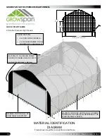
Страница 46: ...in material sku MATERIAL TO COVER END FRAME AND DOOR FRAME AREAS DCC4931 See dark shaded areas in diagram MATERIAL FOR THE ROLL UP DOOR PANELS QED108181 MATERIAL FOR DROP DOWN ROLL UP SIDES DD084Hxxx...

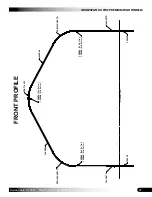
Страница 47: ...e 01 08 21 108179_80_81_82_83_84H FRONT PROFILE 102675 102675 102856 End Rafter 102548 Mid Rafter 102856 End Rafter 102548 Mid Rafter 102856 End Rafter 102548 Mid Rafter 20G166SS401D 20G166SS401D 20GT...

Страница 48: ...bly ATTENTION TO PREVENT DAMAGE AND POSSIBLE INJURY INSTALL THE ANTI BILLOW ROPE IN SHORT LENGTHS ALONG EACH SIDE OF THE FRAME DO NOT INSTALL AS A SINGLE LENGTH TIED AT EACH END DOING SO WILL RESULT I...

Страница 49: ...Ground Level ATTENTION TO PREVENT DAMAGE AND POSSIBLE INJURY INSTALL THE ANTI BILLOW ROPE IN SHORT LENGTHS ALONG EACH SIDE OF THE FRAME DO NOT INSTALL AS A SINGLE LENGTH TIED AT EACH END DOING SO WIL...

Страница 50: ...el ATTENTION TO PREVENT DAMAGE AND POSSIBLE INJURY INSTALL THE ANTI BILLOW ROPE IN SHORT LENGTHS ALONG EACH SIDE OF THE FRAME DO NOT INSTALL AS A SINGLE LENGTH TIED AT EACH END DOING SO WILL RESULT IN...

Страница 51: ...evel ATTENTION TO PREVENT DAMAGE AND POSSIBLE INJURY INSTALL THE ANTI BILLOW ROPE IN SHORT LENGTHS ALONG EACH SIDE OF THE FRAME DO NOT INSTALL AS A SINGLE LENGTH TIED AT EACH END DOING SO WILL RESULT...

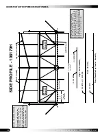
Страница 52: ...bly QH1304 Strut Angle Purlin Assembly Length 72 0 4 0 Rafter S on center on center pacing 4 131S075 Angle Purlin Assembly 1 131P0135 11 131S075 Purlin Assembly 1 131P0735 13 131S075 Drop Down Roll up...

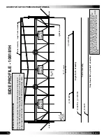
Страница 53: ...ENTION TO PREVENT DAMAGE AND POSSIBLE INJURY INSTALL THE ANTI BILLOW ROPE IN SHORT LENGTHS ALONG EACH SIDE OF THE FRAME DO NOT INSTALL AS A SINGLE LENGTH TIED AT EACH END DOING SO WILL RESULT IN A LOO...

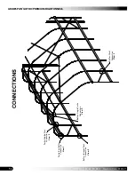
Страница 54: ...4 108179_80_81_82_83_84H Revision date 01 08 21 CONNECTIONS View 3 View 1 Rafter Angle Purlin Connection View 5 Rafter Strut Connection View 4 Rafter Ground Post Connection Purlin Mid Rafter Connectio...

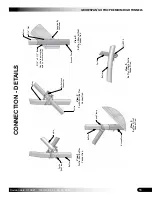
Страница 55: ...nnection Purlin End Rafter View 5 Rafter Angle Purlin View 1 Connection Purlin Mid Rafter Rafter Ground Post View 2 Connection Purlin Rafter Purlin End Clamp 5 16 x 2 1 2 Bolt Rafter 5 16 Nut Supplied...

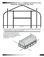
Страница 56: ...t the end wall frame as shown with the vertical jambs extending above the header 18 to 24 This provides an anchor point for cables if you decide to install them now or in the future Header CUSTOMER SU...

Страница 57: ...e details on page 18 Threaded rod and rafter are not shown Roll up door panel is not shown 104188B 1 2 bolt FALB08B nut FAME09B washer FAK16 ROD cut FALB04B nuts FAME08B washer CUSTOMER SUPPLIED END F...

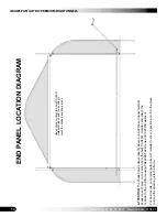
Страница 58: ...ver the shaded end frame areas ATTENTION The shaded areas above identify where to install the end panel material Measure each area cut a section from the bulk DCC4931 material and attach the material...

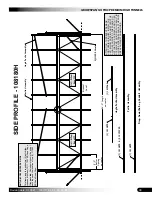
Страница 59: ...8 3 4 6 8 3 4 4 11 16 6 5 Ground Level Over The Top 38 9 1 2 465 1 2 Ribbon Board Height Do not install above this line When installing the side purlins allow enough space above the clamps and purlin...

Страница 60: ...734 Band Clamp Pulley Rope Baseboard The above photo shows a typical drop down side panel as installed on a sample building This photo applies to buildings equipped with drop down sides only It does n...

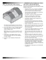
Страница 61: ...d panel frame to support the panel during winter months and strong winds Secure horizontal support using pins for easy removal Vertical bracing can remain throughout the year if spaced according to ne...

Отзывы: