35
GROWSPAN
™
GOTHIC PREMIUM HIGH TUNNELS
Revision date: 01.08.21 108179_80_81_82_83_84H
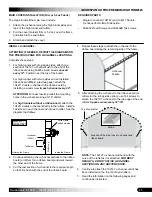
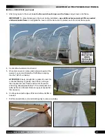
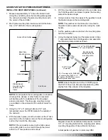
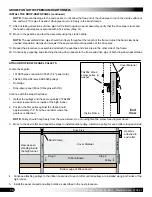
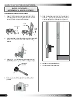
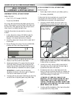
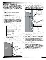
3. Next, insert 3/8" threaded rod through mounting hole
and attach using a 3/8" nut and washer on each side.
Tighten.
Install so most of the rod extends outside high
tunnel.
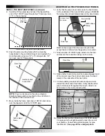
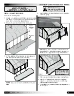
4. Place guide channel in position and mark where
threaded rod end meets channel.
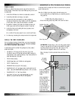
TWIST-OF-THE-WRIST ASSEMBLY
ATTENTION:
Lower end of channel will "float" slightly
above ground when installed at correct height. Lower
end is not anchored.
Do not allow channel end to
contact ground.
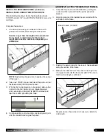
5. Drill 3/8" hole through guide channel and secure using
3/8" nut on each side.
Do not tighten at this time.
6. Continue with next procedure.
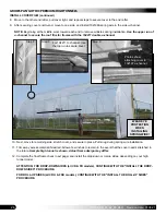
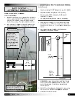
Mounting hole
location to anchor
guide channel.
Upper end of guide
can remain (as
shown), or trimmed
a few inches above
mounting point.
See dashed line in
photo.
Guide Channel
End of channel to remain a few
inches above ground to allow
for movement during operation.
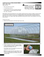
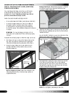
Complete these steps:
1. At building end where roll-up gearbox will be located,
take one guide channel (102570) and use it to mark
mounting hole location. See photo below. Excess
channel length above threaded rod is removed later.
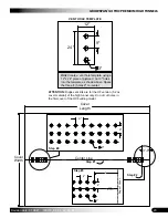
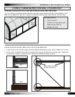
2. After marking hole position, drill a 3/8" hole through
end panel and end rafter
. See diagram (lower left).
Gather the parts:
• Aluminum channel (102570) and drive handle (102480)
• Gearbox (103496) and gearbox drive (102717)
• Mounting plate (103544), bearing (102569), and
threaded rod (FAK26)
• 3/8" nuts (FALB04B) and 3/8" washers (FAME08B)
Guide
Channel
(102570)
End of
Channel
Above
Ground
Step 3
Ground Level
4"- 6"
Threaded
Rod
(FAK26)
ROLL-UP SIDES —
ASSEMBLY & INSTALLATION
End
Rafter

