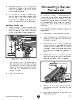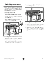
-16-
g0679 stroke/Edge sander
5
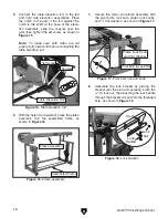
. Connect the table elevation rod to the left
and right side elevation assemblies. place
the notch in the end of the rod against the
notch in the shaft at the base of the eleva-
tion assembly, slide the coupler over the
joint, then tighten the set screw, as shown in
figure 15
.
Note:
To make sure both sides are set
evenly, fully lower both before connecting the
table elevation rod.
6
. With the help of an assistant, place the platen
assembly onto the assembled frame, as
shown in
figure 16
.
7
. secure the motor and platen assembly with
the pivot bolts, lock nuts, platen lock knobs,
and
1
⁄
2
" flat washers, as shown in
figure 17
.
figure 15.
Table elevation rod.
figure 16.
Platen assembly.
table Elevation rod
Coupler
set screw
platen assembly
assembled Frame
8
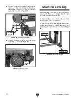
. assemble the lock bracket by placing the
bracket over the stud and securing it with the
1
⁄
2
"-13 lock nut, then inserting the lock handle
through the bracket slot and into the threaded
hole, as shown in
figure 18
.
figure 17.
Pivot bolt, nut, and knob.
pivot Bolt & lock nut
platen lock Knob
and Flat Washer
figure 18.
Lock bracket.
HijY
AdX`
Cji
AdX`
=VcYaZ
Содержание G0679
Страница 15: ...G0679 Stroke Edge Sander 13 Hardware Recognition Chart...
Страница 42: ...40 G0679 Stroke Edge Sander Main Breakdown SECTION 9 PARTS...
Страница 44: ...42 G0679 Stroke Edge Sander Belt Idler Wheel Assembly Breakdown...
Страница 47: ...G0679 Stroke Edge Sander 45 Right Upright Assembly Breakdown...
Страница 49: ...G0679 Stroke Edge Sander 47 Left Upright Assembly Breakdown...


