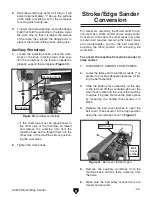
g0679 stroke/Edge sander
-17-
9
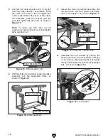
. attach the two belt cover latch assemblies to
the platen assembly frame with (4)
1
⁄
4
-20 x
1
⁄
2
flange bolts, as shown in
figure 19
.
10
. Connect the idler wheel assembly to the plat-
en assembly frame with (4)
5
⁄
16
-18 x
1
⁄
2
flange
bolts, as shown in
figure 20
.
12
. open the platen cover, align it with the idler
wheel cover, then secure the two together
with (3)
1
⁄
4
-20 x
1
⁄
2
flange bolts and (3)
1
⁄
4
-20
hex nuts, as shown in
figure 22
. Close and
latch the platen cover.
figure 19.
Lid latches.
figure 20.
Idler wheel assembly.
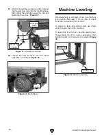
figure 21.
Idler wheel box.
figure 22.
Platen cover connection.
platen assembly Frame
idler Wheel
assembly
11
. secure the idler wheel box to the platen
assembly with (2)
5
⁄
16
-18 x
1
⁄
2
flange bolts and
5
⁄
16
-18 hex nuts, as shown in
figure 21
.
platen assembly
Frame
idler Wheel
assembly
idler Wheel
Cover
Belt Cover
latch
assembly
platen assembly
Flange Bolts
Flange Bolts
Содержание G0679
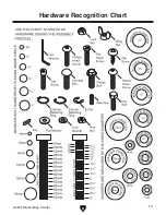
Страница 15: ...G0679 Stroke Edge Sander 13 Hardware Recognition Chart...
Страница 42: ...40 G0679 Stroke Edge Sander Main Breakdown SECTION 9 PARTS...
Страница 44: ...42 G0679 Stroke Edge Sander Belt Idler Wheel Assembly Breakdown...
Страница 47: ...G0679 Stroke Edge Sander 45 Right Upright Assembly Breakdown...
Страница 49: ...G0679 Stroke Edge Sander 47 Left Upright Assembly Breakdown...


