70
Adjusting the throttle and collective pitch curves
Practical procedure
Although the throttle and collective pitch control systems
are based on separate servos, they are always operated
in parallel by the throttle / collective pitch stick (except
when autorotation is invoked). The Helicopter program
automatically couples the functions in the required way.
In the mx-16s program the trim lever of control function
1 only affects the throttle servo, i.e. it acts as idle trim
(see “Digital trims” on page 26).
The process of adjusting throttle and collective pitch cor-
rectly, i.e. setting the motor’s power curve to match the
collective pitch setting of the main rotor blades, is the
most important aspect of setting up any model helicop-
ter. The program of the mx-16s provides independent
adjustment facilities for the throttle, collective pitch and
torque compensation curves.
These curves can be defi ned using a maximum of fi ve
reference points. To defi ne the control curves all you
have to do is set individual values for these fi ve points
on the travel of the throttle / collective pitch stick.
However, before you set up the throttle / collective pitch
function it is important to adjust the mechanical linkages
to all the servos accurately, in accordance with the set-
up notes provided by the helicopter manufacturer.
Note:
The hover point should always be set to the centre
position of the throttle / collective pitch stick.
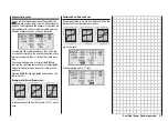
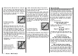
The diagram shows a curve with
a slightly altered throttle setting
below the hover point at the centre
of stick travel.
Idle setting and throttle curve
The idle setting is adjusted solely with the throttle limi-
ter closed, using the trim lever of the C1 function. Re-
ference point “1” of the throttle curve defi nes the thrott-
le setting when the helicopter is in a descent, but without
affecting the hover setting.
This is a case where you can exploit fl ight phase pro-
gramming to use different throttle curves. An increased
system rotational speed below the hover point proves to
be useful in certain circumstances, for example for fast,
steep landing approaches with greatly reduced collecti-
ve pitch, and for aerobatics.
Heli mixer – Model helicopter
Different throttle curves are programmed for each fl ight
phase, so that you can use the optimum set-up both for
hovering and aerobatics:
• Low system rotational speed with smooth, gentle
control response and low noise at the hover.
• Higher speed for aerobatics with motor power set-
tings close to maximum. In this case the throttle cur-
ve also has to be adjusted in the hover range.
1 2 3 4 5
C o n t r o l T r a v e l
O
u
tp
u
t
+ 1 0 0 %
- 1 0 0 %
In 8
(Input 8)
The adjustment facilities in this line of the menu are only
relevant if your model helicopter is fi tted with a speed
governor (regulator) which maintains a constant system
rotational speed. The settings should then be carried out
in accordance with the instructions supplied with the go-
vernor you intend to use.
Содержание MX-16S
Страница 1: ...1...
Страница 17: ...17...
Страница 31: ...31 Fixed wing models Installation and connections...
Страница 35: ...35 Program description Reserving a new memory...
Страница 47: ...47 Base settings Model helicopter...
Страница 83: ...83 Fail safe...
Страница 89: ...89 Programming examples Fixed wing model...
Страница 109: ...109 Programming examples Model helicopter...
Страница 112: ...112 112...
Страница 116: ...116...


