60
Phase trim
Flight phase-specifi c trims for fl aps, ailerons and elevator
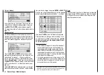
sition switch SW 6/7, then it is advisable to assign it to
“Phase 2” and “Phase 3” at the extremes, with «normal»
at the centre position.
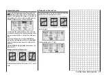
(At the centre position of SW 6/7 the switch symbols on
the screen should look as in the picture below.)
Once the switches are set, you should assign names
to the switch positions, e.g.: switch “up” from centre =
“Launch”; switch “back” from centre = “Speed”, etc..
You can select from the following names:
• takeoff
• thermal
• dist(ance)
• speed
• aerobat(ic)
• landing
• air-tow
• test
Once assigned, these names will appear in the
transmitter’s basic display, and in the »
Phase trim
«
menu.
Setting up fl ight phase trims
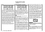
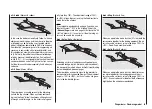
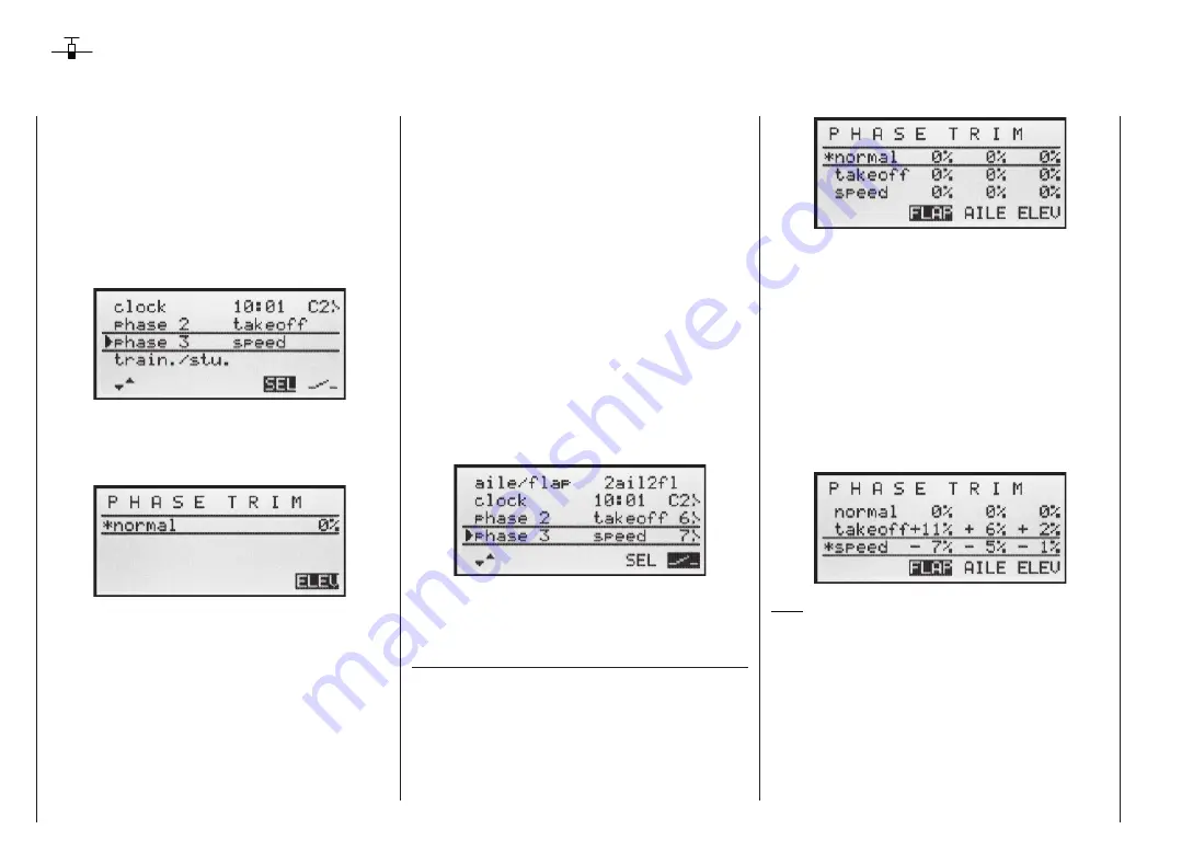
In the »Phase trim« menu you can adjust the trims for
the previously selected fl ight phases.
The fi rst step is to switch to the phase which you wish to
adjust (the * at far left indicates the currently active pha-
se).
If you have not assigned a switch to “Phase 2” and / or
“Phase 3” in the “Base settings” menu, i.e. you have not
assigned names and switches to these alternative pha-
ses, you automatically remain in fl ight phase 1 «nor-
mal».
The number and name of this fl ight phase are perma-
nently assigned, and cannot be altered. For this re-
ason the “normal” phase is not stated as Phase 1 in the
»
Base settings
« menu; it is simply hidden.
If you select the »
Phase trim
« menu with this basic ar-
rangement, i.e. without setting up fl ight phases, you will
fi nd just the «normal» line on the screen, whose pre-set
values of 0% are not usually changed.
If you wish to enter values other than “0”, e.g. to have
more lift at launch, or to be able to fl y more slowly when
thermalling, or faster when fl ying speed tasks, but
WITHOUT having to change the base settings each
time, then you need to use alternative fl ight phases. This
is done by activating “Phase 2” and, if necessary, “Pha-
se 3” in the »
Base settings
« menu.
To do this you move to the »
Base settings
« menu and
assign a relevant name and switch to “Phase 2” and (if
required) “Phase 3”. If you decide to use the three-po-
Select the desired control function using the right-hand
rocker button, then hold the
SELECT
button pressed in
and set the required trim values using the right-hand ro-
cker button.
You can activate the different phases by operating the
assigned phase select switch or switches. Note that the
servos do not change from one setting to another ab-
ruptly; they move smoothly with a transition time of
around one second.
Values can be set within the range -125% to +125%.
However, typical values are normally in single fi gures or
low double fi gures.
Note:
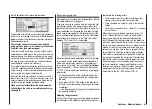
When setting up “Phase trim”, only “ELE”, “AIL” and
“ELE” will be available on the screen, or – as shown
above – “FLAP”, “AIL” and “ELE”; this depends on the in-
formation you have entered in the “Aileron / fl ap” line of
the »
Base settings
« menu.
Phase trim – Fixed-wing model
Содержание MX-16S
Страница 1: ...1...
Страница 17: ...17...
Страница 31: ...31 Fixed wing models Installation and connections...
Страница 35: ...35 Program description Reserving a new memory...
Страница 47: ...47 Base settings Model helicopter...
Страница 83: ...83 Fail safe...
Страница 89: ...89 Programming examples Fixed wing model...
Страница 109: ...109 Programming examples Model helicopter...
Страница 112: ...112 112...
Страница 116: ...116...

