61
What is a mixer?
The basic function
In many models it is often desirable to use a mixer to
couple various control systems, e.g. to link the ailerons
and rudder, or to inter-connect a pair of servos where
two control surfaces are actuated by separate servos. In
all these cases the signal which fl ows directly from the
“output” of a transmitter stick to the associated servo is
“bled off” at a particular point, and the derived signal is
then processed in such a way that it affects the “input” of
another control channel, and therefore eventually ano-
ther receiver output.
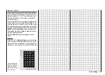
Example:
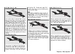
Controlling two elevator servos using the elevator stick.
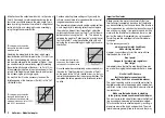
Note: 0% ... +125% = same course and -125% ... 0% = against course
The mx-16s transmitter software contains a large num-
ber of pre-programmed coupling functions as standard,
which are designed to mix together two (or more) control
channels. The mixer required in this example is supplied
“ready-made”, and just has to be activated in the softwa-
re in the “tail” line of the »
Base settings
« menu in the
form of “2 EL Sv”.
The software also includes three freely programmable li-
near mixers in the fi xed-wing and helicopter programs,
all of which can be used in each model memory.
For more information please refer to the general notes
on “Free mixers” in the section of this manual starting on
page 76.
Wing mixers
(The display varies according to the information you
have entered in the “Motor at C1” and “Ail / Flap” lines in
the »
Base settings
« menu.)
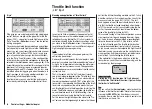
The mx-16s transmitter’s program contains a series of
pre-programmed coupling functions, and all you have
to do is set the mixer ratios and (optionally) assign a
switch. The number of pre-programmed mixer functions
in the mixer list will vary according to the pre-set “mo-
del type” (tail type, number of wing servos, with or wit-
hout motor – see the section starting on page 38). For
example, if your model is not fi tted with camber-chan-
ging fl aps, and you have not entered any fl ap servos
in the »
Base settings
« menu, all the fl ap mixers in the
program are automatically suppressed, as are the “Bra-
ke
NN” mixers if you enter “Idle front” or “Idle rear”
in the “Motor at C1” line. This makes the menus clearer
and easier to understand, and also avoids potential pro-
gramming errors.
Notes:
The position of the camber-changing fl aps in the indivi-
dual fl ight phases is primarily determined in the
»Pha-
se trim«
menu; see left page. However, if you wish to be
able to adjust these settings in fl ight, or in general terms
control the fl aps manually, any transmitter control assig-
ned to input “E6” (in the »
Control settings
« menu – see
page 52) can be used.
This transmitter control then operates the two fl ap ser-
vos connected to receiver outputs 6 and 7, provided that
fl ap servos have already been set up in the “Ail / Fl” line
of the »
Base settings
« menu.
Note:
If a transmitter control is assigned to input “E7”, it will be
de-coupled by the software if two camber-changing fl aps
are defi ned; this is intentional, as it eliminates the dan-
ger of errors when a fl ap command is given.
Basic programming procedure
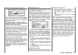
1. Hold the
SELECT
button pressed in, then use the
right-hand rocker button to select the desired mixer.
Dependent from the mixer, only SEL or additional
is shown in the lower display line.
2. Use the right-hand rocker button to select one of the-
se two fi elds.
3. Press the
SELECT
button. The appropriate input fi eld
is now highlighted.
4. Set the desired value using the right-hand rocker but-
ton, and assign a switch if required.
Negative and positive parameter values are possible;
this may be necessary to obtain the correct direction
of servo rotation (control surface defl ection).
CLEAR
sets a changed value in the inverse fi eld
back to thedefault value.
5. Press
SELECT
to conclude the input process.
Wing mixers – Fixed-wing model
3
3
8
Se
rv
o
4,
8 V
C 57
7
Be
s
t.
-N
r.
4
1
0
1
Se
rv
o
4,
8 V
C 57
7
Be
s
t.
-N
r.
4
1
0
1
Transmitter
control
Control function
output
Control channel
(receiver output)
Mixer
menus
Mixer
Servo 1
Servo 2
Содержание MX-16S
Страница 1: ...1...
Страница 17: ...17...
Страница 31: ...31 Fixed wing models Installation and connections...
Страница 35: ...35 Program description Reserving a new memory...
Страница 47: ...47 Base settings Model helicopter...
Страница 83: ...83 Fail safe...
Страница 89: ...89 Programming examples Fixed wing model...
Страница 109: ...109 Programming examples Model helicopter...
Страница 112: ...112 112...
Страница 116: ...116...


