GL820-UM-251-9370
4-14
4. SETUP PROCEDURES
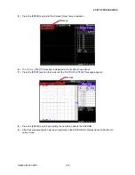
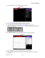
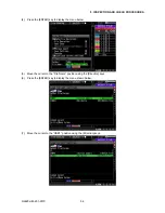
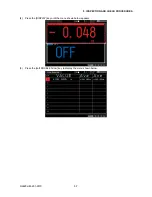
(5) Press the [ENTER] key to start the Setup3 (RTD temp.) operation.
Message
(6) The "
0 ohm : [START]
" message is displayed at the location shown above.
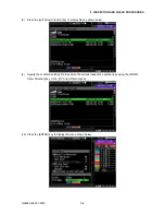
(7) Connect the reference 0 Ω resistor to the input terminals of channel 20.
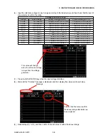
(8) Press the [START] key and then wait until the "
350 ohm : [START]
" message appears.
Replace the reference resistor to correspond to one of the displayed resistors in the following table and
then press the [START] key.
Message
Reference resistor
0 ohm
0 Ω
350 ohm
350 Ω
2500 ohm
2500 Ω
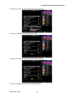
(9) Repeat step (8) by sequentially to 350 Ω and 2500 Ω.
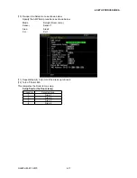
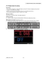
(10) The "EEPROM : [ENTER]" message appears when the 2500 ohm setup was completed.
Message
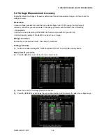
(11) Press the [ENTER] key to begin writing the new Setup data to the EEPROM.
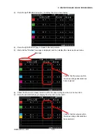
(12) After the setup parameters have been registered to the EEPROM, the display closes and returns to
normal mode.
Содержание GL820
Страница 1: ...midi LOGGER SERVICE MANUAL 820 GL820 UM 251 GL820 UM 251 02 9370 ...
Страница 2: ......
Страница 8: ...GL820 UM 251 9370 1 2 1 CONFIGURATION ...
Страница 12: ......
Страница 35: ...GL820 UM 251 9370 4 15 4 SETUP PROCEDURES 13 Turn off the GL820 This completes the RTD temp setup ...
Страница 36: ......
Страница 56: ......


