GL820-UM-251-9370
4-6
4. SETUP PROCEDURES
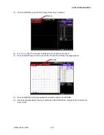
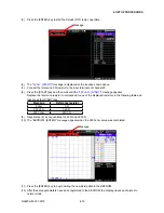
(5) Press the [ENTER] key to start the Setup1 (Basic) operation.
Message
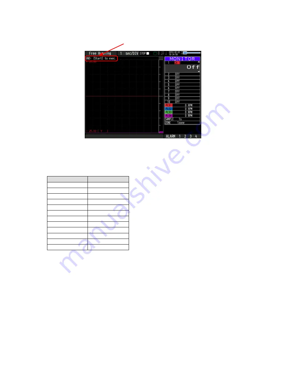
(6) The “
GND : [START]
” message is displayed at the location shown above.
(7) Input “0.000mV” to the input terminals of channel 1.
(8) Press the [START] key and then wait until the "
20 mV : [START]
" message appears.
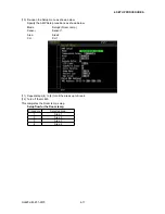
Specify the voltage generator's output voltage setting to correspond to one of the displayed voltage
ranges in the following table, and then input that voltage to the GL820.
Message
Input Voltage
GND
0.000 mV
20 mV
20.000 mV
50 mV
50.000 mV
100 mV
100.000 mV
200 mV
200.000 mV
500 mV
500.000 mV
1 V
1.000 V
2 V
2.000 V
5 V
5.000 V
10 V
10.000 V
20 V
20.000 V
50 V
50.000 V
(9) Repeat step (8) by sequentially setting the Measure parameter to 50 mV, 100 mV, 200 mV, 500 mV, 1 V,
2 V, 5 V, 10 V, 20 V and 50 V, and then inputting the corresponding voltage.
Содержание GL820
Страница 1: ...midi LOGGER SERVICE MANUAL 820 GL820 UM 251 GL820 UM 251 02 9370 ...
Страница 2: ......
Страница 8: ...GL820 UM 251 9370 1 2 1 CONFIGURATION ...
Страница 12: ......
Страница 35: ...GL820 UM 251 9370 4 15 4 SETUP PROCEDURES 13 Turn off the GL820 This completes the RTD temp setup ...
Страница 36: ......
Страница 56: ......


