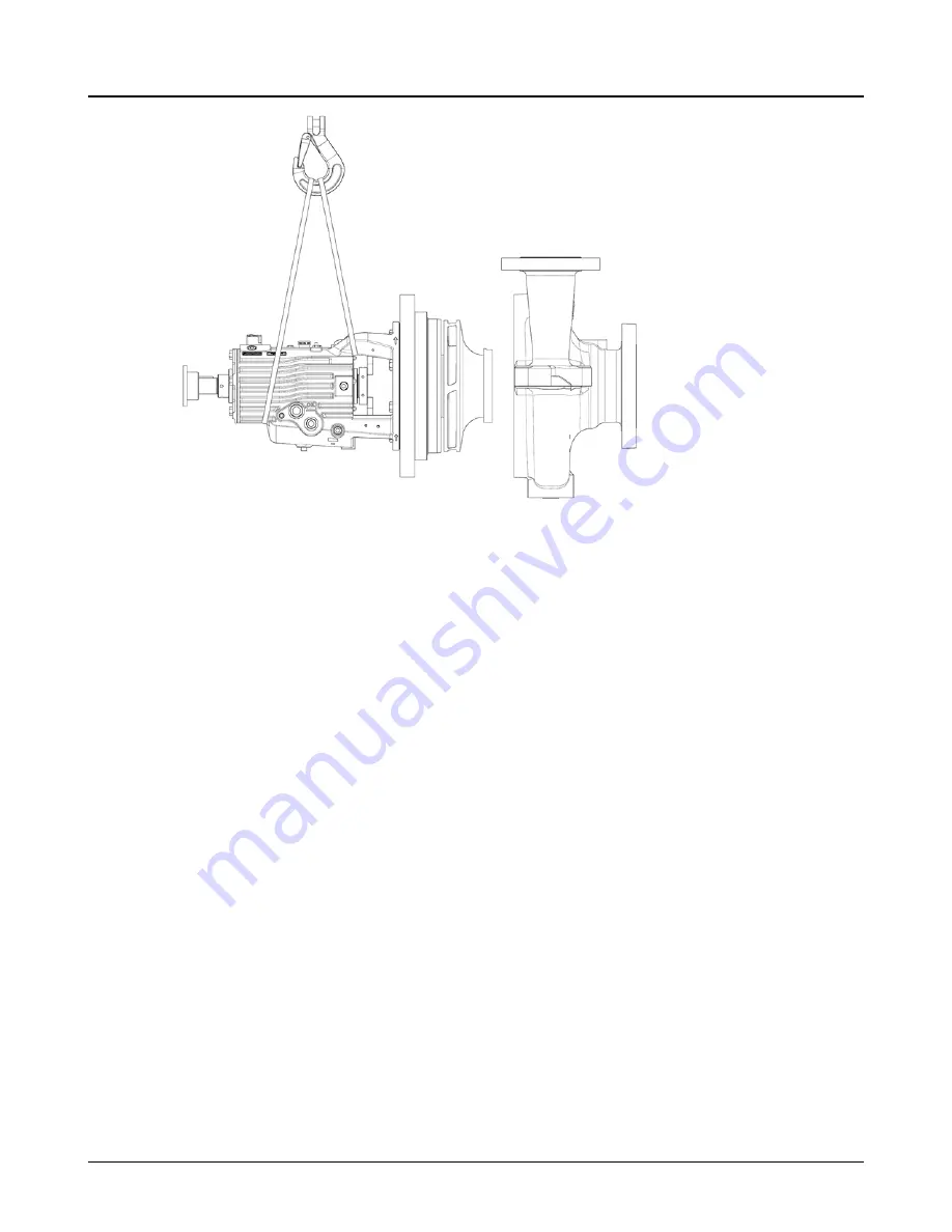
Figure 78: Back pull-out assembly
3.
Slide the back pull-out assembly into the proper position in the casing.
Make sure that the casing gasket is not damaged.
4.
Install the casing casing washers (533) and stud nuts (425).
5.
Inspect the gap between the seal-chamber cover and casing and adjust the casing stud nuts as
necessary to make the gap uniform.
6.
Tighten the casing stud nuts uniformly, using an alternating pattern, until the seal-chamber cover is
in metal-to-metal contact with the casing. Tighten each nut to the torque values shown in the Maxi-
mum torque values for 3700i fasteners table.
7.
Verify that the shaft turns freely.
If you detect any rubbing or excessive drag, then determine the cause and correct it.
8.
Reinstall the coupling spacer, coupling guard, auxiliary piping, tubing, and equipment that was re-
moved during preparation for disassembly.
9.
Lubricate the bearings.
6.6.8 Install the Venturi Insert (Venturi casings only)
1.
Place gasket (351O) onto venturi insert (100W).
2.
Install the venturi insert (100W) into the casing (100) so that the through hole is in the vertical orien-
tation and the notch faces up toward the discharge flange.
3.
Install the venturi insert studs (362A) and hex nuts (362B) to the casing (100). Tighten the nuts
(362B) in an alternating pattern until the insert flange is metal to metal with the casing (100). Tight-
en each nut to the torque values shown in the maximum torque values table.
6.6 Reassembly
108
Model 3700i API610 / Type OH2 Installation, Operation, and Maintenance Manual


