


Chapter 8 - Adjustments
Upper and Lower Limit Switch Adjustment
Under normal conditions the Upper and Lower Limit Switches should not require adjustment in the
fi
eld unless one
were to fail and require replacement. These switches are set in the factory during assembly and
fi
nal testing. There
could be situations however that would require a slight adjustment.
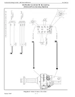
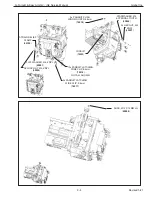
The Limit Switch Assembly is located inside the actuator, on the side the wire rope exits the center casting. You must
remove the Front Cover (short cover) to access this area. Refer to
diagram 1
below.
Diagram 1
Upper Limit Switch
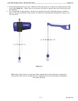
The bottom allen head screw adjusts the upper limit. Use a 5mm allen wrench to perform the adjustment. Turning the
screw clockwise raises the stop point of the wire rope. Counterclockwise lowers the stop point of the wire rope. A full
turn is approximately 3 inches of wire rope travel. Refer to the side view in
diagram 2
below.
Diagram 2
Lower Limit Switch
The lower limit is a result of the wire rope replacement position. When this switch is actuated there should be approxi-
mately two full turns of wire rope left on the drum. There is no adjustment for this position. The switch provides protec-
tion for the hardware inside the actuator. Refer to
diagram 2
above.
G-Force® & Easy Arm Q2 - iQ2 Service Manual
Gorbel Inc.
Revised 5/21
8 - 1
Содержание G-Force iQ2 Series
Страница 2: ...G Force Easy Arm Q2 iQ2 Service Manual Gorbel Inc Revised 5 21 0 1 This page intentionally left blank...
Страница 4: ...G Force Easy Arm Q2 iQ2 Service Manual Gorbel Inc Revised 5 21 0 3 This page intentionally left blank...
Страница 19: ...This page is intentionally left blank G Force Easy Arm Q2 iQ2 Service Manual Gorbel Inc Revised 5 21 5 5...
Страница 42: ...This page is intentionally left blank G Force Easy Arm Q2 iQ2 Service Manual Gorbel Inc Revised 5 21 7 3...
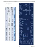
Страница 43: ...ACTUATOR PCB GEN 2 G Force Easy Arm Q2 iQ2 Service Manual Gorbel Inc Revised 5 21 7 4...
Страница 45: ...This page is intentionally left blank G Force Easy Arm Q2 iQ2 Service Manual Gorbel Inc Revised 5 21 7 6...
Страница 83: ...G Force Easy Arm Q2 iQ2 Service Manual Gorbel Inc Revised 5 21 9 30 This page is intentionally left blank...
Страница 105: ...G Force Easy Arm Q2 iQ2 Service Manual Gorbel Inc Revised 5 21 9 52 This page is intentionally left blank...
Страница 111: ...G Force Easy Arm Q2 iQ2 Service Manual Gorbel Inc Revised 5 21 9 58 Remote Force Sensing Hub SEE CHART 1...
Страница 112: ...G Force Easy Arm Q2 iQ2 Service Manual Gorbel Inc Revised 5 21 9 59 FSH HUB Options...
Страница 113: ...G Force Easy Arm Q2 iQ2 Service Manual Gorbel Inc Revised 5 21 9 60 This page is intentionally left blank...
Страница 119: ...G Force Easy Arm Q2 iQ2 Service Manual Gorbel Inc Revised 5 21 9 66 Diagram G 1a G360 with Air Assembly and Disassembly...
Страница 120: ...G Force Easy Arm Q2 iQ2 Service Manual Gorbel Inc Revised 5 21 9 67 Diagram G 1b G360 Assembly and Disassembly...
Страница 121: ...G Force Easy Arm Q2 iQ2 Service Manual Gorbel Inc Revised 5 21 9 68 This page is intentionally left blank...
Страница 136: ...G Force Easy Arm Q2 iQ2 Service Manual Gorbel Inc Revised 5 21 9 83 This page is intentionally left blank...


