


22
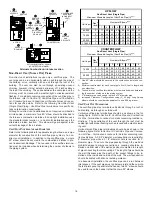
2. Remove and save the two screws securing the junction box
to the side panel.
3. Relocate junction box and associated plugs and grommets
to opposite side panel. Secure with screws removed in step
2.
*
*
*
*
*
*
*
*
*
STANDARD
JUNCTION BOX
LOCATION
ALTERNATE
JUNCTION BOX
LOCATION
Junction Box Relocation
WARNING
T
O AVOID THE RISK OF INJURY, ELECTRICAL SHOCK OR DEATH, THE FURNACE
MUST BE ELECTRICALLY GROUNDED IN ACCORDANCE WITH LOCAL CODES OR,
IN THEIR ABSENCE, WITH THE LATEST EDITION OF THE
N
ATIONAL
E
LECTRIC
C
ODE.
To ensure proper unit grounding, the ground wire should run from
the furnace ground screw located inside the furnace junction box all
the way back to the electrical panel.
NOTE:
Do not use gas piping
as an electrical ground. To confirm proper unit grounding, turn off
the electrical power and perform the following check.
1. Measure resistance between the neutral (white) connection
and one of the burners.
2. Resistance should measure 10 ohms or less.
This furnace is equipped with a blower door interlock switch which
interrupts unit voltage when the blower door is opened for servicing.
Do not defeat this switch.
24 V
OLT
T
HERMOSTAT
W
IRING
NOTE:
Wire routing must not interfere with circulator blower
operation, filter removal, or routine maintenance.
As a two-stage furnace, the furnace integrated control module pro-
vides terminals for both “W1” and “W2”, and “YLO” and “Y” thermo-
stat connections. This allows the furnace to support the following
system applications: ‘Two-Stage Heating Only’, ‘Two-Stage Heat-
ing with Single-Stage Cooling’, and ‘Two-Stage Heating with Two-
Stage Cooling’. Refer to the following figures and table for proper
connections to the integrated control module.
Low voltage connections can be made through either the right or left
side panel. Thermostat wiring entrance holes are located in the
blower compartment. Wire routing must not interfere with circulator
blower operation, filter removal, or routine maintenance.
W
G
Y
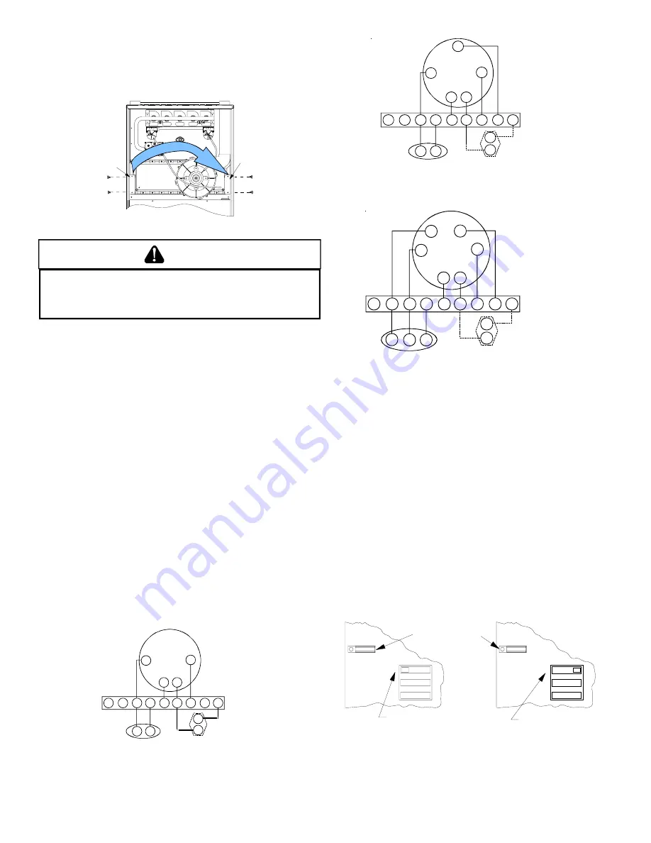
Single-Stage Heating with Single-Stage Cooling
R
B/C
G
R
W1
W2
O
YLO
Y
DEHUM
TWIN
Y
C
NEU
HOT
Furnace Integrated
Control Module
Thermostat
Single-Stage Heating
with
Single-Stage Cooling
(
)
Remote
Condensing Unit
(Single-Stage Cooling)
Dehumidistat
[Optional]
NOTE: To apply a single-stage heating thermostat, the
thermostat selector jumper on the integrated Control
module
must
be set on single stage.
W1
G
Y
Two-Stage Heating with Single-Stage Cooling
R
W2
B/C
G
R
W1
W2
O
YLO
Y
DEHUM
TWIN
Y
C
NEU
HOT
Furnace Integrated
Control Module
Thermostat
Two-Stage Heating
with
Single-Stage Cooling
(
)
Remote
Condensing Unit
(Single-Stage Cooling)
Dehumidistat
[Optional]
G
Y
Two-Stage Heating with Two-Stage Cooling
R
B/C
G
R
W1
W2
O
YLO
Y
DEHUM
TWIN
NEU
HOT
Furnace Integrated
Control Module
Thermostat
Two-Stage Heating
with
Two-Stage Cooling
(
)
Remote
Condensing Unit
(Two-Stage Cooling)
Dehumidistat
[Optional]
Y
C
YLO
YLO
W2
W1
Thermostat Diagrams
This furnace is equipped with a 40 VA transformer to facilitate use
with most cooling equipment. Consult the wiring diagram, located
on the blower compartment door, for further details of 115 Volt and
24 Volt wiring.
S
INGLE
-S
TAGE
T
HERMOSTAT
A
PPLICATION
A single-stage thermostat with only one heating stage can be used
to control this furnace. The application of a single-stage thermostat
does not offer “true” thermostat-driven two-stage operation, but pro-
vides a
timed
transition from low to high fire. The furnace will run on
low stage for a fixed period of time before stepping up to high stage
to satisfy the thermostat’s call for heat. The delay period prior to
stepping up can be set at either 5 or 10 minutes through the DIP
switch adjacent to the Heat Off delay DIP switches on the integrated
control module. To use a single-stage thermostat, turn off power to
the furnace, move the thermostat selection jumper on the integrated
control module from the “two-stage” position to the “single-stage”
position, turn power back on. Refer to the following figures.
3
2
1
T
W
O
S
I
N
G
L
E
TSTAT
OFF
3
2
1
T-Stat selection jumper in
single-stage thermostat
position.
DIP switch position 3: ON
Delay Period: 10 minutes.
DIP switch position 3: OFF
Delay Period: 5 minutes.
T
W
O
S
I
N
G
L
E
TSTAT
ON
24 V
OLT
D
EHUMIDISTAT
W
IRING
The optional usage of a dehumidistat allows the furnace’s circulator
blower to operate at a slightly lower speed during a combined ther-
mostat call for cooling and dehumidistat call for dehumidification.
This lower blower speed enhances dehumidification of the condi-
Содержание GCV9 Series
Страница 36: ...36...