


15
hose clamps from the drain kit bag, attach the vent/flue pipe
and coupling to the induced draft blower. Secure the coupling
to the cabinet using the screws removed in step 1 or with
field-supplied 3/8” #8 self drilling screws.
WARNING
T
HE RUBBER ELBOW IS NOT DESIGNED TO SUPPORAT A LOAD.
W
HEN THE
RUBBER ELBOW IS MOUNTED EXTERNALLY TO THE FURNACE CABINET,
EXTREME CARE MUST BE TAKEN TO ADEQUATELY SUPPORT FIELD-SUPPLIED
VENT/FLUE PIPING, AS DAMAGE CAN RESULT IN LEAKS CAUSING BODILY
INJURY OR DEATH DUE TO EXPOSURE TO FLUE GASES, INCLUDING CARBON
MONOXIDE.
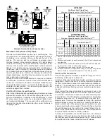
7.
Upflow
and
Counterflow
units
.
For
upright installations
, externally mount the rubber elbow
to the vent/flue coupling using a worm gear hose clamp.
Secure field supplied vent/flue piping to the rubber elbow
using a worm gear hose clamp.
NOTE:
Use of the alternate
vent/flue location for upright installations, requires the drain
trap be installed on the same side of the unit as the flue pipe.
8.
Upflow
and
Counterflow
units
.
For
horizontal installations
, externally secure the field-
supplied vent/flue pipe directly to the vent/flue coupling using
a PVC or ABS coupling or elbow.
5
ADDITIONAL PLUG
FROM DRAIN KIT
7
EXTERNALLY
MOUNT
RUBBER ELBOW
6
SECURE TO
ID BLOWER WITH
RUBBER COUPLING
AND HOSE
CLAMPS
COUNTERFLOW/UPRIGHT
(UPFLOW SIMILAR)
UPFLOW
REMOVE
4 SCREWS
3
REMOVE
PIPE
2
DETACH RUBBER
ELBOW FROM
ID BLOWER AND
VENT/FLUE
PIPE
1.
REMOVE
4 SCREWS
2
DETATCH RUBBER
ELBOW FROM
ID BLOWER AND
VENT/FLUE
PIPE
COUNTERFLOW
3
REMOVE
PIPE
5
REMOVE
AND RELOCATE
5
REMOVE
AND RELOCATE
1
REMOVE
3 SCREWS
1
UPFLOW/HORIZONTAL
(COUNTERFLOW SIMILAR)
6
SECURE TO
ID BLOWER WITH
RUBBER COUPLING
AND HOSE
CLAMPS
6
SECURE TO
CABINET WITH
SCREWS
Alternate Vent/Flue Location
A
LTERNATE
C
OMBUSTION
A
IR
I
NTAKE
L
OCATION
The alternate combustion air intake location consists of a large,
unobstructed hole (alternate vent connection is aligned with the
Induced Draft Blower). To use the alternate combustion air intake
location, refer to the following steps, and the “Alternate Combus-
tion Air Intake Location” figure.
NOTE:
Counterflow unit instructions follow the upflow instructions.
1. Remove and save the four screws securing the combustion
air intake coupling to the furnace’s top panel (upflow).
Counterflow
units.
Remove and save the four screws securing the combustion
air intake coupling to the basepan. Remove an additional
three screws securing the furnace’s internal combustion air
intake pipe to the blower deck.
2. Remove the combustion air intake coupling and gasket from
the top panel.
Counterflow
units.
Remove the combustion air intake pipe from the furnace and
cut the pipe at the basepan coupling. Save the basepan
coupling and gasket from the blower deck coupling for use
in the alternate location. Discard the remaining pipe.
3. Remove plastic plug from alternate combustion air intake
location. Relocate and install plug in standard air intake
location (top cover).
Counterflow
units.
Remove plastic plug from alternate combustion air intake
location. Relocate and install plug in standard air intake
location (basepan). Plug the remaining hole in the blower
deck with the plastic plug included in the drain kit bag.
4.
Upflow
and
Counterflow
units.
With the gasket facing the cabinet side panel, and the flange’s
flat spot facing forward, secure the combustion air intake
coupling to the cabinet using the screws removed in step 1
or with field-supplied 3/8” #8 self -drilling screws.
CAUTION
B
E SURE NOT TO DAMAGE INTERNAL WIRING OR OTHER COMPONENTS WHEN
REINSTALLING COUPLING AND SCREWS.
5.
Upflow
and
Counterflow
units.
For
non-direct vent installations
installed
horizontally
, a
minimum of one 90° elbow should be installed on the
combustion air intake coupling to guard against inadvertent
blockage. No elbow is required on the alternate combustion
air intake of
upright
installations, however, a minimum
clearance of 2 inches is required to assure proper air supply.
6.
Upflow
and
Counterflow
units.
For
direct vent installations
, secure field-supplied
combustion air intake pipe directly to the air intake coupling.
NOTE:
A PVC coupling or elbow is required on counterflow
units.
Содержание GCV9 Series
Страница 36: ...36...