


17
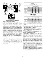
12 " Min To
Roof Or
Highest Anticipated
Snow Level
TEE
Vertical Termination (Single Pipe)
12" MIN.
TO ROOF OR
HIGHEST
ANTICIPATED
SNOW LEVEL
90º
MEDIUM RADIUS
ELBOWS
Alternate Vertical Termination (Single Pipe)
MIN.
12"
FROM
WALL
12"
TO GROUND OR
HIGHEST ANTICIPATED
SNOW LEVEL
WALL
INSIDE
OUTSIDE
TEE
or
90°ELBOW
TURNED
DOWN
COUPLING
ELBOW OR
COUPLING
Horizontal Termination (Single Pipe)
VENT/FLUE TEE
or
90° ELBOW TURNED
DOWN
12" MIN. ABOVE
HIGHEST ANTICIPATED
SNOW LEVEL
12" MIN.
Horizontal Termination (Single Pipe)
Above Highest Anticipated Snow Level
D
IRECT
V
ENT
(D
UAL
P
IPE
) P
IPING
The inlet air screens provided in the installation instruction packet
are available for the installer to use in the inlet of the combustion air
pipe to prevent animals from building nests in the combustion air
pipe. Installation of screens, while strongly recommended, is not
required and will not affect performance of the unit.
Direct vent
installations require both a combustion air intake and a
vent/flue pipe. The pipes may be run horizontally and exit through
the side of the building or run vertically and exit through the roof of
the building. The pipes may be run through an existing
unused
chimney; however, they must extend a minimum of 12 inches above
the top of the chimney. The space between the pipes and the chim-
ney must be closed with a weather tight, corrosion resistant flash-
ing. Both the combustion air intake and a vent/flue pipe termina-
tions must be in the same atmospheric pressure zone. Refer to
Section IX, Vent/Flue and Combustion Air Pipe - Termination Loca-
tions or Concentric Vent Termination
for specific details on termina-
tion construction. For details concerning connection of pipes to the
furnace, refer to the
Section IX, Vent/Flue Pipe and Combustion
Pipe - Standard Furnace Connections or Alternate Furnace Con-
nections.
V
ENT
/F
LUE
AND
C
OMBUSTION
A
IR
P
IPE
L
ENGTHS
AND
D
IAMETERS
Refer to the following table for applicable length, elbows, and pipe
diameter for construction of the vent/flue and combustion air intake
pipe systems of a direct vent (dual pipe) installation. The number of
elbows tabulated represents the number of elbows and/or tees in
each (Vent/Flue & Combustion Air Intake) pipe. Elbows and/or tees
used in the terminations must be included when determining the
number of elbows in the piping systems.
If the combustion air intake pipe is to be installed above a finished
ceiling or other area where dripping of condensate will be objection-
able, insulation of the combustion air pipe may be required. Use
1/2” thick closed cell foam insulation such as Armaflex™ or Insul-
tube™ where required.
1
2
3
4
5
6
7
8
Standard
2
71
68
65
62
59
56
53
50
Alternate
2
58
55
52
49
46
43
40
37
2
49
46
43
40
37
34
31
28
3
71
68
65
62
59
56
53
50
2
36
33
30
27
24
21
18
15
3
57
54
51
48
45
42
39
36
Standard
3
71
68
65
62
59
56
53
50
Alternate
3
57
54
51
48
45
42
39
36
Standard
3
49
46
43
40
37
34
31
28
Alternate
3
35
32
29
26
23
20
17
14
1
2
3
4
5
6
7
8
2
49
46
43
40
37
34
31
28
3
71
68
65
62
59
56
53
50
2
36
33
30
27
24
21
18
15
3
57
54
51
48
45
42
39
36
2
61
58
55
52
49
46
43
40
3
71
68
65
62
59
56
53
50
2
48
45
42
39
36
33
30
27
3
57
54
51
48
45
42
39
36
90,000
Standard
Alternate
70,000
Standard
Alternate
COUNTERFLOW
Direct Vent (Dual Pipe)
Maximum Allow able Length
of Vent/Flue & Combustion Air Intake Pipe (ft)
Unit Input
(Btu)
Termination
Style
Pipe
(4)
(inch)
Number of Elbow s
(1)(2)(3)(5)
45,000
90,000
115,000
Termination
Style
70,000
Standard
Alternate
UPFLOW
Direct Vent (Dual Pipe)
Maximum Allow able Length
of Vent/Flue & Combustion Air Intake Pipe (ft)
Number of Elbow s
(1)(2)(3)(5)
Pipe
(4)
(inch)
Unit Input
(Btu)
1) Elbows and/or tees used in terminations must be included when deter-
mining quantity of allowable elbows in the system.
2) Number of elbows tabulated are for each (Vent/Flue & Combustion Air
Intake) pipe.
3) Minimum requirements for each Vent/Flue & Combustion Air Intake pipe
is five (5) feet in length and one elbow/tee.
4) 3” diameter pipe can be used in place of 2” diameter pipe.
5) Increased Clearance Configurations using (2) 45 deg. Long Sweep el-
bows should be considered equivalent to one 90 deg. elbow.
Содержание GCV9 Series
Страница 36: ...36...