Goodman GCV9 Series Скачать руководство пользователя страница 13

13

12"

Non-Direct Vent

Vent/Flue Termination

No Terminations
 Above Walkway

12"

min.

4'

min.

Non-Direct Vent

Vent/Flue Termination

Direct Vent

Vent/Flue Termination

<10'

Forced Air

Inlet

Non-Direct Vent

&

Direct Vent

Vent/Flue Terminations

Grade or Highest

 Anticipated 
Snow Level

3' min.

12" min.

4' min.

12" min.

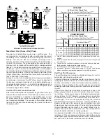
Vent Termination Clearances

NOTE:

 In Canada, the Canadian Fuel Gas Code takes precedence

over the preceding termination restrictions.

C

ANADIAN

 V

ENTING

 R

EQUIREMENTS

In Canada, venting must conform to the requirements of the current
CAN/CSA-B149 Installation Code.  Use only CSA listed two or three
inch diameter PVC or ABS pipe, solvent cement, and fittings through-
out.  Carefully follow the pipe manufacturers’ instructions for cut-
ting, cleaning, and solvent cementing PVC and/or ABS.
The vent can be run through an existing unused chimney provided
the space between the vent pipe and the chimney is insulated and
closed with a weather-tight, corrosion-resistant flashing.

S

TANDARD

 F

URNACE

 C

ONNECTIONS

It is the responsibility of the installer to ensure that the piping con-
nections to the furnace are secure, airtight, and adequately sup-
ported.
As shipped, attachment “couplings” for vent/flue and combustion
air intake pipe connections are provided on the furnace’s top cover
(upflow) or basepan (counterflow).  To use the standard connec-
tions, field supplied vent/flue pipe and combustion air intake pipe
(when applicable) should be secured directly to the furnace at these
locations.

V

ENT

/F

LUE

 P

IPE

Vent/flue pipe can be secured to the vent/flue coupling using the
rubber coupling and worm gear hose clamps provided with this fur-
nace (see “Standard Connections” figure).  The rubber coupling al-
lows separation of the vent/flue pipe from the furnace during servic-
ing. Combustion Air and Vent piping should be routed in a manner
to avoid contact with refrigerant lines, metering devices, conden-
sate drain lines, etc.  If necessary, clearances may be increased
by utilizing two 45 deg. Long-Sweep Elbows and creating an “S”
joint to provide additional space at connection locations.  This joint
can be rotated on the fitting to establish maximum clearance be-
tween refrigerant lines, metering devices, and condensate drain
lines, etc.  This joint is the equivalent of one 90 deg. elbow when
considering elbow count.

drain system.  Allowances should be made for minor expansion
and contraction due to temperature variations.  For this reason,
particular care must be taken to secure piping when a long run is
followed by a short offset of less than 40 inches.
Precautions should be taken to prevent condensate from freezing
inside the vent/flue pipe and/or at the vent/flue pipe termination.  All
vent/flue piping exposed to freezing temperatures below 35°F for
extended periods of time must be insulated with 1/2” thick closed
cell foam.  Also all vent/flue piping exposed outdoors in excess of
the terminations shown in this manual (or in unheated areas) must
be insulated with 1/2”  thick closed cell foam.  Inspect piping for
leaks prior to installing insulation.

T

ERMINATION

 L

OCATIONS

NOTES:

 Refer to 

Section IV, Location Requirements and

Considerations

 for combustion air contaminant restrictions.

The following bullets and diagram describe the restrictions concern-
ing the appropriate location of vent/flue pipe and combustion air
intake pipe (when applicable) terminations.  Refer to 

Non-Direct

Vent (Single Pipe) Piping

 and 

Direct Vent (Dual Pipe) Piping

 lo-

cated in this section for specific details on termination construction.

All terminations (flue and/or intake) must be located at
least 12 inches above ground level or the anticipated snow
level.

Vent terminations (non-direct and direct vent) must
terminate at least 3 feet above any forced air inlet located
within 10 feet.

NOTE:  This provision does not apply to the
combustion air intake termination of a direct vent
application.

The vent termination of a 

non-direct


vent

 application must

terminate at least 4 feet below, 4 feet horizontally from, or
1 foot above any door, window, or gravity air inlet into any
building.

The vent termination of a 

direct vent

 application must

terminate at least 12 inches from any opening through
which flue gases may enter a building (door, window, or
gravity air inlet).

The vent termination of vent pipe run vertically through a
roof must terminate at least 12 inches above the roof line
(or the anticipated snow level) and be at least 12 inches
from any vertical wall (including any anticipated snow build
up).

A vent termination shall not terminate over public walkways
or over an area where condensate or vapor could create
a nuisance or hazard or could be detrimental to the
operation of regulators, relief valves, or other equipment.

The combustion air intake termination of a direct vent
application should not terminate in an area which is
frequently dusty or dirty.

Содержание GCV9 Series

Страница 1: ...han when the unit is in operation Remember it is your responsibility to install the product safely and to know it well enough to be able to instruct a customer in its safe use Safety is a matter of co...

Страница 2: ...ES 12 TERMINATION LOCATIONS 13 CANADIAN VENTING REQUIREMENTS 13 STANDARD FURNACE CONNECTIONS 13 ALTERNATE FURNACE CONNECTIONS 14 NON DIRECT VENT SINGLE PIPE PIPING 16 DIRECT VENT DUAL PIPE PIPING 17 V...

Страница 3: ...cuit Description 33 GENERAL 33 INTEGRATED CONTROL MODULE 33 PRIMARY LIMIT 33 AUXILIARY LIMIT 33 ROLLOUT LIMIT 33 PRESSURE SWITCHES 33 FLAME SENSOR 33 XVIII Troubleshooting 33 ELECTROSTATIC DISCHARGE E...

Страница 4: ...warranty certificate is also supplied with the unit Read the warranty carefully and note what is covered Keep the warranty certificate in a safe location for future reference If additional informatio...

Страница 5: ...itch 24 Inductor Not All Models 25 Two Stage Integrated Control Module with fuse and diagnostic LED 26 24 Volt Thermostat Connections 27 Transformer 40 VA 28 ECM Variable Speed Circulator Blower 29 Au...

Страница 6: ...ion are replaced The input rate and temperature rise are set per the furnace rating plate The input rate and temperature rise are set per the furnace rating plate 100 outside air is provided for combu...

Страница 7: ...ems Do not install the furnace where the combustion air is exposed to the following substances chlorinated waxes or cleaners chlorine based swimming pool chemicals water softening chemicals deicing sa...

Страница 8: ...rrected Corrections must be in accordance with the latest edition of the Na tional Fuel Gas Code NFPA 54 ANSI Z223 1 and or CSA B149 In stallation Codes printing inks paint removers varnishes hydrochl...

Страница 9: ...red a part of the unconfined space 5 3 3 Equipment Located in Confined Spaces a All Air from Inside the Building The confined space shall be pro vided with two permanent openings communicating directl...

Страница 10: ...ree area in 5 3 3 consideration shall be given to the block ing effect of louvers grilles or screens protecting openings Screens used shall not be smaller than 1 4 inch mesh If the area through a desi...

Страница 11: ...ed for the drain trap Additionally the appropriate downward piping slope must be maintained from the drain trap to the drain location Refer to Section X Condensate Drain Trap and Lines for further det...

Страница 12: ...is the responsibility of the installer to follow the manufacturers recommendations and to verify that all vent flue piping and connec tors are compatible with furnace flue products Additionally it is...

Страница 13: ...es should be made for minor expansion and contraction due to temperature variations For this reason particular care must be taken to secure piping when a long run is followed by a short offset of less...

Страница 14: ...t flue and combustion air intake piping run vertically from the side of the cabinet NOTE Standard and alternate locations can be combined i e an installation may use the standard combustion air intake...

Страница 15: ...tion refer to the following steps and the Alternate Combus tion Air Intake Location figure NOTE Counterflow unit instructions follow the upflow instructions 1 Remove and save the four screws securing...

Страница 16: ...be in stalled on the inside and outside of the wall The wall penetration should be sealed with silicone caulking material In a basement installation the vent flue pipe can be run between joist spaces...

Страница 17: ...er for construction of the vent flue and combustion air intake pipe systems of a direct vent dual pipe installation The number of elbows tabulated represents the number of elbows and or tees in each V...

Страница 18: ...LEVEL Standard Horizontal Terminations Dual Pipe 24 MAX 3 MIN 24 MAX AIR INTAKE 90 MEDIUM RADIUS ELBOW 12 MIN ABOVE HIGHEST ANTICIPATED SNOW LEVEL Alternate Horizontal Vent Termination Dual Pipe SUPPO...

Страница 19: ...d through the right or left side panel and into the drain trap secured to the outside of the cabinet NOTE Refer to Section X Condensate Drain Lines and Drain Trap Alternate Vent Flue Hose Connections...

Страница 20: ...p 2 Secure drain trap to side panel at the mounting holes dimples or crosshairs on counterflow models located below the grommet drain holes 3 Attach PVC drain line to drain trap outlet with either a 9...

Страница 21: ...NG ANY ELECTRICAL WIRING CAUTION LABEL ALL WIRES PRIOR TO DISCONNECTION WHEN SERVICING CONTROLS WIRING ERRORS CAN CAUSE IMPROPER AND DANGEROUS OPERATION VERIFY PROPER OPERATION AFTER SERVICING WIRING...

Страница 22: ...e Condensing Unit Single Stage Cooling Dehumidistat Optional NOTE To apply a single stage heating thermostat the thermostat selector jumper on the integrated Control module must be set on single stage...

Страница 23: ...eaner 1 0 Amp maximum at 120 VAC Turn OFF power to the furnace before installing any accessories Follow the humidifier or air cleaner manufacturers instructions for locating mounting grounding and con...

Страница 24: ...ring the gas supply pressure and manifold pressure are provided on the valve The gas valve has a manual ON OFF control located on the valve itself This control may be set only to the ON or OFF positio...

Страница 25: ...opane gas leak Rust can reduce the level of odorant in propane gas Do not rely on your sense of smell Contact a local propane connection is 375 in lbs excessive over tightening may damage the gas valv...

Страница 26: ...ng a pair of seamer pliers or seamer tongs NOTE Airflow area will be reduced by ap proximately 18 if duct flanges are not unfolded This could cause performance issues and noise issues WARNING EDGES OF...

Страница 27: ...ds If the furnace is installed without filters the warranty will be voided On upflow units guide dimples locate the side return cutout locations Use a straight edge to scribe lines connecting the dimp...

Страница 28: ...h an ignition device which automatically lights the burner Do not try to light the burner by hand 5 Move the furnace gas valve manual control to the OFF position 6 Wait five minutes then smell for gas...

Страница 29: ...w 8 Remove regulator cover screw from the low LO outlet pressure regulator adjust tower and turn screw clockwise to increase pressure or counterclockwise to decrease pressure 9 Energize main M solenoi...

Страница 30: ...t High Stage Heat Tap Model 390 520 715 930 600 800 1100 1430 840 920 1000 1080 1210 1325 1440 1555 A B C D 520 715 910 1170 800 1100 1400 1800 1125 1195 1265 1335 1620 1720 1820 1920 A B C D 520 715...

Страница 31: ...to enhance cooling performance and increase comfort level The ramping profiles are selected using DIP switches 5 and 6 Refer to the following figure for switch positions and their corresponding taps...

Страница 32: ...e monitors flame presence Gas valve will remain open only if flame is detected If the thermostat call is for low heat gas valve and induced draft blower will continue on low stage If the call is for h...

Страница 33: ...etected will take the necessary precau tions and provide diagnostic information through an LED PRIMARY LIMIT The primary limit control is located on the partition panel and moni tors heat exchanger co...

Страница 34: ...r leakage Check the outside termination and the connections at and internal to the furnace Heat exchanger Check for corrosion and or buildup within the heat exchanger passageways Burners Check for pro...

Страница 35: ...9 Clean residue from furnace using a vacuum cleaner 10 Replace the parts removed in the previous steps in reverse order 11 Turn on electrical power and gas to furnace Check for leaks and proper unit...

Страница 36: ...36...

Страница 37: ...Inspect pressure switch hose Repair if necessary Inspect flue and or inlet air piping for blockage proper length elbows and termination Check drain system Correct as necessary Correct pressure switch...

Страница 38: ...emove obstruction Check circulator blower speed and performance Correct speed or replace blower if necessary Check burners for proper alignment Check flue and air inlet piping for blockage proper leng...

Страница 39: ...OLS SINGLE CONTROL ON 45 kBTU PK PINK PLUG CONNECTION BURNER COMPARTMENT BLOWER COMPARTMENT VT IGNITER 2 MANUFACTURER S SPECIFIED REPLACEMENT PARTS MUST BE USED WHEN SERVICING PK YL 5 FLASHES FLAME SE...

Страница 40: ...40 2004 2006 Goodman Manufacturing Company L P 2550 North Loop West Suite 400 Houston TX 77092 www goodmanmfg com...

Отзывы: