


26 / 60
Artikel-Nr. 15 513 50 c
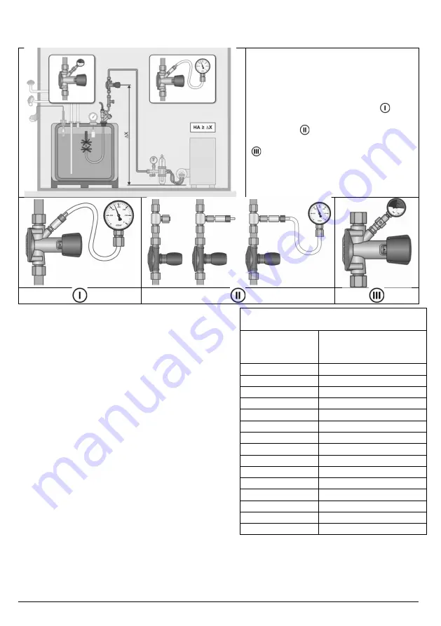
Figure 5: Version 2:
Simulation of a line rupture through pressure measurement on the
anti-siphon device
The function check is also possible
without removing the distiller hose line
by measuring the vacuum directly
after the diaphragm-controlled anti-
siphon device. Either you directly use
the factory-set test connection or
you equip the suction line with a test
connection .
A pressure gauge, e.g. a manometer
which is subject to test equipment
monitoring, is to be used for the
pressure measurement.
For this functional check it is necessary to comply
with the following steps:
Hydrostatic pressure of the fuel oil
column depending on the height
Connect the pressure gauge.
1. Successfully complete leak testing with test
vacuum -300mbar.
2. In the event of the subsequent assembly of a
test connection in the oil line, the actual
hydrostatic pressure of the fuel oil column also
has to be calculated po,g at the height of ∆X+
instead of the height ∆X.
3. Refer to the table for the hydrostatic pressure
of fuel oil column
p
o,g
.
4. Calculate the minimum permitted closing
pressure of the safety equipment against
siphoning
p
o,
= (
p
o,g
+ 5) • (-1) [mbar].]
Height ∆X
(∆X+)
in [mm]
p
o,g
in [mbar]
fuel oil EL
0.50
42
0.75
63
1.00
84
1.25
10
1.50
12
1.75
14
2.00
16
2.25
19
2.50
21
2.75
232
3.00
253
3.25
274
3.50
295
3.75
317
4.00
337
Comment 1:
The closing pressure of the diaphragm-controlled anti-siphon device must always be above the
value of the hydrostatic pressure of fuel oil column p
o,g
and is set in the factory. The safety
allowance selected for this purpose totals 5mbar acc. EN 12514.


