Part No. 139378
Z-30/20N • Z-30/20N RJ • Z-34/22 • Z-34/22N
4 - 41
June 2011
Section 4 • Repair Procedures
REV B
7-4
Valve Coils
How to Test a Coil
A properly functioning coil provides an
electromotive force which operates the solenoid
valve. Critical to normal operation is continuity
within the coil that provides this force field.
Electrocution/burn hazard. Contact
with electrically charged circuits
could result in death or serious
injury. Remove all rings, watches
and other jewelry.
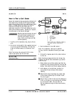
1 Tag and disconnect the wiring from the coil to
be tested.
2 Test the coil resistance.
Coils with 2 terminals:
Connect the leads from
the ohmmeter to the valve coil terminals.
Coils with 1 terminal:
Connect the positive
lead from the ohmmeter to the valve coil
terminal, then connect the negative lead from
the ohmmeter to the internal ring of the valve
coil.
Result: The resistance should be within
specification, plus or minus 30%.
Result: If the resistance is not within
specification, plus or minus 30%, replace the
coil.
Valve Coil Resistance
Specification
Note: The following coil resistance specifications
are at an ambient temperature of 68°F / 20°C. As
valve coil resistance is sensitive to changes in air
temperature, the coil resistance will typically
increase or decrease by 4% for each 18°F / 10°C
that your air temperature increases or decreases
from 68°F / 20°C.
Valve Coil Resistance Specification
Description
Specification
Solenoid valve, 3 position 4 way, 20V DC
22
Ω
(schematic items A, J, K, U, V, Y, AA, BB and CC)
Proportional solenoid valve, 24V DC
19.5
Ω
(schematic item H)
Solenoid valve, N.C. poppet, 20V DC
23.5
Ω
(schematic item M)
Solenoid valve, N.O. poppet, 20V DC
23.5
Ω
(schematic item P)
MANIFOLDS
Содержание Z-30/20N
Страница 1: ......
Страница 4: ...Z 30 20N Z 30 20N RJ Z 34 22 Z 34 22N PartNo 139378 June2011 iv This page intentionally left blank...
Страница 148: ...6 46 June2011 Section 6 Schematics 6 45 Power Cable Wiring Diagram...
Страница 149: ...6 47 Section 6 Schematics June2011 6 48 Drive Contactor Panel Wiring Diagram...
Страница 152: ...6 50 June2011 Section 6 Schematics Manifold and Limit Switch Wiring Diagram 6 49...
Страница 153: ...6 51 Section 6 Schematics June2011 6 52 LVI BCI Option Wiring Diagram...
Страница 156: ...6 54 June2011 Section 6 Schematics 6 53 Charger Interlock Option...
Страница 157: ...6 55 Section 6 Schematics June2011 6 56 CTE Option CE Models...
Страница 160: ...6 58 June2011 Section 6 Schematics Hydraulic Schematic 6 57...

