6 - 2
Z-30/20N • Z-30/20N RJ • Z-34/22 • Z-34/22N
Part No. 139378
June 2011
Section 6 • Schematics
REV A
Electrical Symbols Legend
+
-
6V DC
Battery
ORG/BLK-1
number
cable
with
color
Wire
Connection
no terminal
P1
Emergency
Stop button
normaly closed
PR4
Relay panel
contactor
Solenoid or
relay coil
Horn
Tilt sensor
NOHC
LS1
Limit switch
normally open
held closed
P3
HORN
Horn button
normally open
T-circuit
connected
LED
AP1
Quick disconnect
terminal
Diode
BLK
FS1
Foot switch
Relay contact
normaly open
Relay contact
normally closed
TS3
ENGINE
ST
AR
T
Toggle switch
SPDT
Circuits crossing
no connection
Auxiliary / Primary
lift pump
PUMP
Boom function
speed controller
WHT
GRN
RED
BP1
BLK/RED
Pressure
switch
PSI
Terminal
TB20
T-circuit
connects at terminal
BLK #21
TB21
Circuit breaker
Drive motor
A2
A1
S1
S2
FB
Flashing
beacon
Hour meter
Fuse
Limit switch
NO
LS3
NC
Toggle switch
DPDT
TS6
RIGHT
LEFT
GRN/BLK
TB17
Ground
supression
circuit
_
HM
+
PLATFORM
GROUND
KS1
Key switch
CR2
30
87
85
86
CR2
30
87
85
86
Содержание Z-30/20N
Страница 1: ......
Страница 4: ...Z 30 20N Z 30 20N RJ Z 34 22 Z 34 22N PartNo 139378 June2011 iv This page intentionally left blank...
Страница 148: ...6 46 June2011 Section 6 Schematics 6 45 Power Cable Wiring Diagram...
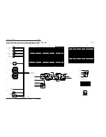
Страница 149: ...6 47 Section 6 Schematics June2011 6 48 Drive Contactor Panel Wiring Diagram...
Страница 152: ...6 50 June2011 Section 6 Schematics Manifold and Limit Switch Wiring Diagram 6 49...
Страница 153: ...6 51 Section 6 Schematics June2011 6 52 LVI BCI Option Wiring Diagram...
Страница 156: ...6 54 June2011 Section 6 Schematics 6 53 Charger Interlock Option...
Страница 157: ...6 55 Section 6 Schematics June2011 6 56 CTE Option CE Models...
Страница 160: ...6 58 June2011 Section 6 Schematics Hydraulic Schematic 6 57...

