background image

3 - 28

Z-30/20N • Z-30/20N RJ • Z-34/22 • Z-34/22N

Part No. 139378

Section 3 • Scheduled Maintenance Procedures

June 2011

REV A

CHECKLIST

D

PROCEDURES

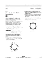
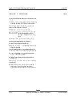
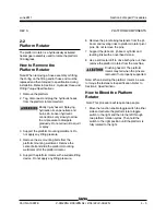
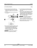
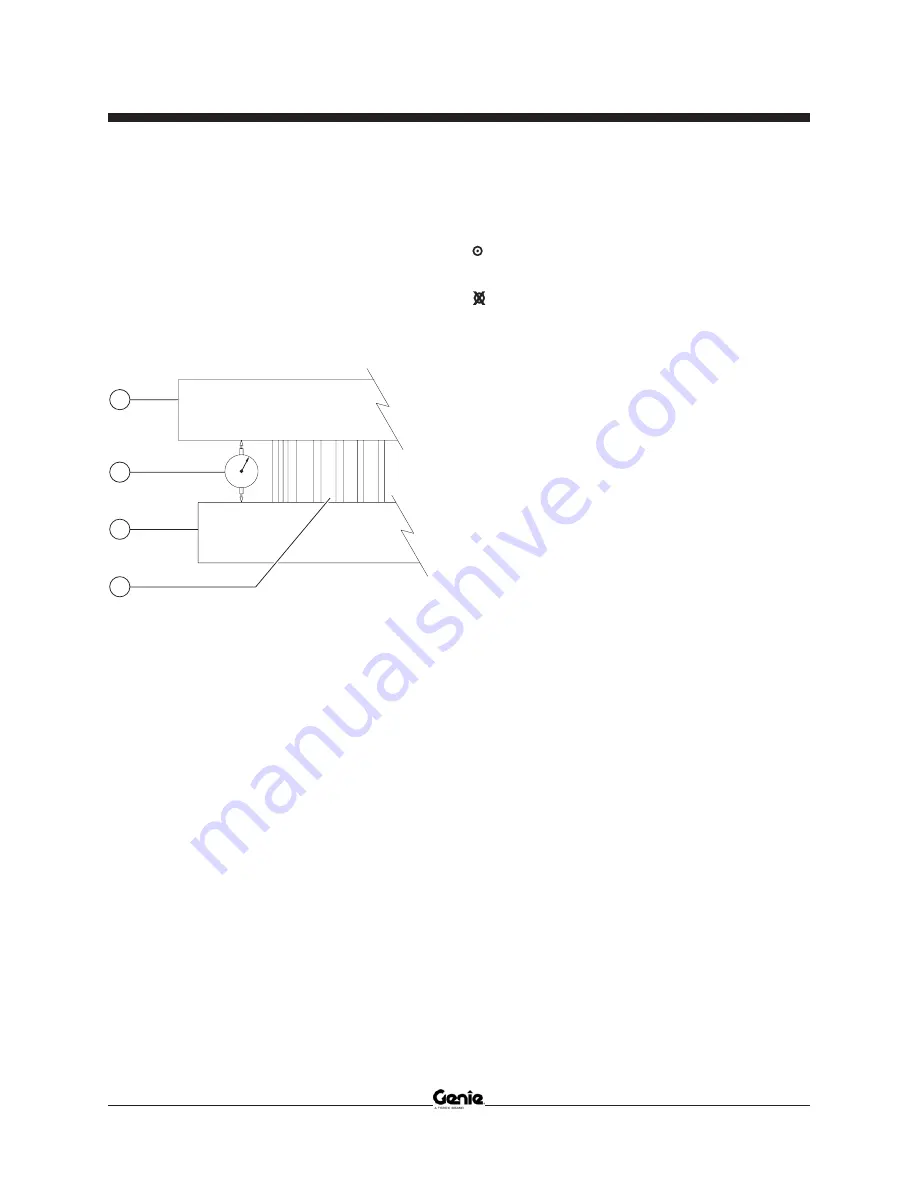
4 Place a dial indicator between the drive chassis

and the turntable at a point that is directly
under, or in line with, the boom and no more
than 1 inch / 2.5 cm from the bearing.

Note: To obtain an accurate measurement, place
the dial indicator no more than 1 inch / 2.5 cm from
the turntable rotation bearing.

a

turntable

b

dial indicator

c

drive chassis

d

turntable rotation bearing

5 Adjust the dial indicator to "0".

6 Lower the secondary boom to the stowed

position and lower the primary boom to a
horizontal position. Fully extend the primary
boom.

7 Note the reading on the dial indicator.

Result: The measurement is less than

0.055 inch / 1.4 mm. The bearing is good.

Result: The measurement is more than

0.055 inch / 1.4 mm. The bearing is worn and
needs to be replaced.

8 Fully retract the primary boom. Raise the

primary and secondary booms to full height.
Visually inspect the dial indicator to be sure the
needle returns to the "0" position.

9 Remove the dial indicator and rotate the

turntable 90°.

10 Repeat steps 4 through 9 until the rotation

bearing has been checked in at least four
equally spaced areas 90° apart.

11 Lower the primary and secondary booms to the

stowed position and turn the machine off.

12 Remove the dial indicator from the machine.

a

b

c

d

Содержание Z-30/20N

Страница 1: ......

Страница 2: ...nrestricted with proper operation inspection and scheduledmaintenance Technical Publications Genie has endeavored to deliver the highest degree of accuracy possible However continuous improvement of o...

Страница 3: ...lb XXX kg Maximum allowable inclination of the chassis 0 deg Gradeability N A Maximum allowable side force XXX lb XXX N Maximum number of platfrm occupants X Model year Manufacture date 04 12 05 2005...

Страница 4: ...Z 30 20N Z 30 20N RJ Z 34 22 Z 34 22N PartNo 139378 June2011 iv This page intentionally left blank...

Страница 5: ...ntified in the operator s manual are also safety hazards when maintenance and repair procedures are performed Do Not Perform Maintenance Unless You are trained and qualified to perform maintenance on...

Страница 6: ...protective clothing if the situation warrants it Be aware of potential crushing hazards such as moving parts free swinging or unsecured components when lifting or placing loads Always wear approved s...

Страница 7: ...anifoldComponentSpecifications 2 4 Machine Torque Specifications 2 4 Hydraulic Hose and Fitting Torque Specifications 2 5 SAE and Metric Fasteners Torque Charts 2 6 Section 3 Rev ScheduledMaintenanceP...

Страница 8: ...in the Drive Hubs and Mounting Bolt Torque 3 14 B 7 Test the Ground Control Override 3 14 B 8 Test the Platform Self leveling 3 15 B 9 Test the Drive Brakes 3 15 B 10 Test the Drive Speed Stowed Posi...

Страница 9: ...ect for Turntable Bearing Wear 3 27 A ChecklistEProcedures E 1 Test or Replace the Hydraulic Oil 3 29 E 2 Grease the Steer Axle Wheel Bearings 3 31 Section 4 Rev RepairProcedures Introduction 4 1 A Pl...

Страница 10: ...4 23 5 2 Secondary Boom Lift Cylinder 4 28 A Hydraulic Pump 6 1 Auxiliary and Function Pump 4 30 B Manifolds 7 1 FunctionManifoldComponents 4 32 7 2 Valve Adjustments Function Manifold 4 36 7 3 Jib B...

Страница 11: ...6 13 B Electrical Schematic CE beforeserialnumbersZ30N10 12119 Z34N10 8857andZ3410 7774 6 16 B Ground Control Box Terminal Strip Wiring Diagram CE beforeserialnumbersZ30N10 12119 Z34N10 8857andZ3410...

Страница 12: ...410 7774 6 40 A Ground Control Box Switch Panel Wiring Diagram AS CE fromserialnumbersZ30N10 12119 Z34N10 8857andZ3410 7774 6 41 A Platform Control Box Wiring Diagram AS CE fromserialnumbersZ30N10 121...

Страница 13: ...g Overall tire diameter 28 in 71 cm Wheel diameter 14 5 in 37 cm Wheel width 7 in 18 cm Wheel lugs Front 8 5 8 18 Rear 9 5 8 18 Lug nut torque dry 125 ft lbs 169 5 Nm Lug nut torque lubricated 95 ft l...

Страница 14: ...seconds Platform rotate 180 5 to 11 seconds Platform level up 14 to 19 seconds Platform level down 13 to 18 seconds Performance Specifications Z 34 22 and Z 34 22N Drive speed maximum Stowed position...

Страница 15: ...stently above 32 F 0 C may result in component damage Note Use Chevron Aviation A hydraulic fluid when ambient temperatures are consistently below 0 F 18 C Note Use Shell Tellus T46 hydraulic oil when...

Страница 16: ...ounting bolts 31 ft lbs 42 Nm SPECIFICATIONS Manifold Component Specifications Plugtorque SAE No 2 36 in lbs 4 Nm SAE No 4 10 ft lbs 13 Nm SAE No 6 14 ft lbs 19 Nm SAE No 8 38 ft lbs 51 Nm SAE No 10 4...

Страница 17: ...ng is seated and retainedproperly 4 Position the tube and nut squarely on the face seal end of the fitting and tighten the nut finger tight 5 Tighten the nut or fitting to the appropriate torque per g...

Страница 18: ...20 3560 4826 3000 4067 5 16 3 8 7 16 1 2 1 1 2 9 16 5 8 3 4 7 8 1 1 1 8 1 1 4 LUBED 1 4 LUBED DRY LUBED DRY LUBED DRY LUBED SAE FASTENER TORQUE CHART Grade 5 DRY LUBED This chart is to be used as a gu...

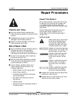
Страница 19: ...forming a series of steps Indicates that an incorrect result has occurred after performing a series of steps Observe and Obey Maintenance inspections shall be completed by a person trained and qualifi...

Страница 20: ...ns that must be performed according to a schedule daily quarterly six months annual and two year The Scheduled Maintenance Procedures Section and the Maintenance Inspection Report have been divided in...

Страница 21: ...tion Tests Use this form to record the results Place a check in the appropriate box after each part is completed Follow the instructions in the operator s manual If any inspection receives an N remove...

Страница 22: ...3 4 Z 30 20N Z 30 20N RJ Z 34 22 Z 34 22N PartNo 139378 Section 3 Scheduled Maintenance Procedures June2011 This page intentionally left blank...

Страница 23: ...ear pads D 2 Free wheel configuration D 3 Turntable bearing bolts D 4 Drive hub oil D 5 Hydraulic return filter D 6 Turntable bearing wear Checklist E Rev A Y N R E 1 Hydraulic oil E 2 Wheel bearings...

Страница 24: ...r hazard and could result in unsafe operating conditions 1 Check to make sure that the operator s and safety manuals are present and complete in the storage container on the platform 2 Examine the pag...

Страница 25: ...ts The pre operation inspection also serves to determine if routine maintenance proceduresarerequired Complete information to perform this procedure is available in the Operator s Manual located on yo...

Страница 26: ...fications require that this procedure be performed every 100 hours Frequent application of lubrication to the turntable bearing and worm drive gear is essential to good machine performance and service...

Страница 27: ...of use may cause the machine to perform poorly and continued use may cause component damage 1 Select the drive hub to be serviced Drive the machine until one of the two plugs is at the lowest point 2...

Страница 28: ...inate corrosion on the battery terminals and cables 3 Be sure that the battery retainers and cable connections are tight 5 Be sure that the battery retainers and cable connections are tight 4 Fully ch...

Страница 29: ...cells is greater than 0 1 OR the specific gravity of one or more cells is 1 172 or less Replace the battery 10 Check the battery acid level If needed replenish with distilled water to 1 8 inch 3 mm b...

Страница 30: ...ground control side turntable cover Harness connector to the drive motor controller located in the non steer end of the drive chassis B 3 Test the Key Switch Note Genie specifications require that thi...

Страница 31: ...ed in a timely fashion 1 Check the tire surface and sidewalls for cuts cracks and unusual wear 2 Check each wheel for damage bends and cracks 3 Check each lug nut for proper torque Refer to Section 2...

Страница 32: ...ifications 4 Install the plugs into the drive hub 5 Check the torque of the drive hub bolts Refer to Section 2 Specifications 6 Repeat this procedure for each drive hub B 7 Test the Ground Control Ove...

Страница 33: ...mes to within 5 degrees B 9 Test the Drive Brakes Note Genie specifications require that this procedure be performed every 250 hours or quarterly whichever comes first Proper brake action is essential...

Страница 34: ...n timing when your reference point on the machine crosses the start line 6 Continue at full speed and note the time when your machine reference point passes over the finish line Refer to Section 2 Spe...

Страница 35: ...ion hold for a moment and then release it Move the jib boom switch to the down position hold for a moment and then release it Result The descent alarm should sound when each switch is held down 3 Turn...

Страница 36: ...ry boom reaches midpoint between the steer tires 3 Rotate the turntable to the right as far as it will go Result Movement should stop when the primary boom reaches midpoint between the steer tires B 1...

Страница 37: ...ine performance and service life Dirty oil and suction strainers may cause the machine to perform poorly and continued use may cause component damage Extremely dirty conditions may require oil changes...

Страница 38: ...thium based or equivalent C 2 Test the Platform Overload System if equipped Note Genie specifications require that this procedure be performed every 500 hours or six months whichever comes first Testi...

Страница 39: ...ght equal to that of the available capacity one of the locations shown Refer to Illustration 1 Result The platform overload indicator lights should be off at both the ground and platform controls and...

Страница 40: ...ound controls Result All ground control functions should not operate 11 Using auxiliary power test all machine functions from the ground controls Result All ground control functions should operate CHE...

Страница 41: ...s 1 Measure each wear pad Replace the wear pad once it reaches the minimum allowable thickness If the wear pad is still within specifications shim as necessary to obtain minimum clearance with zero bi...

Страница 42: ...mage hazard If the machine must be towed do not exceed 2 mph 3 2 km h 1 Chock the steer wheels to prevent the machine from rolling 2 Center a lifting jack of ample capacity 15 000 lbs 7000 kg under th...

Страница 43: ...the lift cylinder safety chock Crushing hazard Keep hands away from the cylinder and all moving parts when lowering the secondary boom Note A lift cylinder safety chock is available through Genie Ser...

Страница 44: ...Install the plugs into the drive hub 6 Repeat this procedure for the other drive hub CHECKLIST D PROCEDURES D 5 Replace the Hydraulic Tank Return Filter Element Note Genie specifications require that...

Страница 45: ...h to either side and move and hold the primary boom toggle switch in the up direction 14 Inspect the filter housing and related components to be sure that there are no leaks CHECKLIST D PROCEDURES D 6...

Страница 46: ...sition and lower the primary boom to a horizontal position Fully extend the primary boom 7 Note the reading on the dial indicator Result The measurement is less than 0 055 inch 1 4 mm The bearing is g...

Страница 47: ...or fitting the O ring on the fitting and or hose end must be replaced and then torqued to specification during installation Refer to Section 2 Hydraulic Hose and Fitting Torque Specifications Note Per...

Страница 48: ...suction strainer from the hydraulic tank and clean it using a mild solvent 9 Rinse out the inside of the tank with a mild solvent 10 Install the suction strainer into the tank 11 Install the lid and...

Страница 49: ...here should be no side to side or up and down movement Skip to step 10 if there is no movement 6 Remove the dust cap from the hub Remove the cotter pin from the castle nut 7 Tighten the castle nut to...

Страница 50: ...or damage to the lip of the seal may occur 17 Fill the hub cavity with clean fresh grease 18 Place the outer bearing into the hub 19 Install the washer and castle nut 20 Tighten the castle nut to 158...

Страница 51: ...osition with the key removed Wheelschocked All external AC power supply disconnected from the machine About This Section Most of the procedures in this section should only be performed by a trained se...

Страница 52: ...function speed controller b drive and brake printed circuit board c drive joystick Boom Function Speed Controller Adjustments Electrocution burnhazard Contact with electrically charged circuits could...

Страница 53: ...e or counterclockwise to decrease the amperage 7 Turn the boom function speed controller to the 9 position 8 Set the max out Press down the foot switch and move the primary boom toggle switch to the d...

Страница 54: ...cks under the platform for support Lower the boom until the platform is resting on the blocks 3 Tag and disconnect the hydraulic hoses to the slave cylinder at the union and connect them together with...

Страница 55: ...ting bolts from the platform mounting weldment Remove the center bolt and slide the platform mounting weldment off of the platform rotator 5 Support the platform rotator with a suitable lifting device...

Страница 56: ...holding the toggle switch until air stops coming out of the bleed valve Close the bleed valve Crushing hazard Keep clear of the platform during rotation 5 Connect the clear hose to the bottom bleed v...

Страница 57: ...off and the alarm does not sound Proceed to step 6 Result The overload indicator lights are flashing at the platform and ground controls and the alarm is sounding Slowly tighten the load spring adjust...

Страница 58: ...ls and the alarm does not sound Remove the additional 10 lb 4 5 kg test weight Repeat this procedure beginning with step 6 Note There may be a 2 second delay before the platform overload indicator lig...

Страница 59: ...hoses or disconnect the wiring Component damage hazard Hoses and cables can be damaged if they are kinked or pinched 6 Models with rotating jib boom Tag disconnect and plug the hydraulic hoses from th...

Страница 60: ...OM COMPONENTS 3 2 Jib Boom Bell Crank models without rotating jib boom How to Remove the Jib Boom Bell Crank Note Perform this procedure with the boom in the stowed position Note When removing a hose...

Страница 61: ...the Jib Boom Rotator Note When removing a hose assembly or fitting the O ring on the fitting and or hose end must be replaced and then torqued to specification during installation Refer to Section 2...

Страница 62: ...d the jib boom rotate toggle switch to the left for approximately 5 seconds then release it Repeat three times 5 Fully rotate the jib boom to the left and continue holding the jib boom rotate toggle s...

Страница 63: ...connections very slowly to allow the oil pressure to dissipate gradually Do not allow oil to squirt or spray 3 Remove the pin retaining fasteners from the jib boom lift cylinder rod end pivot pin Do n...

Страница 64: ...e damaged if it is twisted 1 Use a slotted screwdriver to pry down on the lower clip a link separation point b lower clip 2 Repeat step 1 for each link 3 To remove a single link open the lower clip Us...

Страница 65: ...llcrank See 3 2 How to Remove the Jib Boom Bellcrank Models with rotating jib boom Remove the jib boom rotator See 3 3 How to Remove the Jib Boom Rotator 5 Tag disconnect and cap the slave cylinder hy...

Страница 66: ...ivot pin Use a soft metal drift to remove the pivot pin Pull the cylinder back and secure it from moving 21 Tag disconnect and plug the extension cylinder hydraulic hoses Cap the fittings on the cylin...

Страница 67: ...d 5 Support the extension tube with an overhead crane at the platform end of the boom Crushing hazard The boom extension tube could fall when removed from the boom if not properly supported 6 Support...

Страница 68: ...lock of wood across the upper secondary boom to support the cylinder when the rod end pin is removed 4 Attach an overhead crane to the primary boom at the platform end for support Raise the primary bo...

Страница 69: ...machine Crushing hazard The primary boom lift cylinder will fall if not properly supported when it is removed from the machine PRIMARY BOOM COMPONENTS 4 4 Extension Cylinder The extension cylinder ext...

Страница 70: ...en it is pulled out of the extension tube Note To make installation of the extension cylinder easier be sure that the cylinder rod is extended 3 to 4 feet 1 m Note During removal the overhead crane st...

Страница 71: ...can penetrate and burn skin Loosen hydraulic connections very slowly to allow the oil pressure to dissipate gradually Do not allow oil to squirt or spray 7 Attach a lifting strap from an overhead cran...

Страница 72: ...4 Repair Procedures REV A Secondary Boom Components Secondary Boom a upper pivot b upper compression arm c mid pivot d compression link e lower secondary boom f lower compression arm g turntable pivot...

Страница 73: ...ables from the primary boom cable track to the platform control box Number each cable and its entry location at the platform control box 7 Open the platform control box 8 Tag and disconnect each wire...

Страница 74: ...rap from the overhead crane approximately 2 feet 60 cm from the platform end of the primary boom Measure from the platform end of the primary boom tube 22 Remove the pin retaining fasteners from the u...

Страница 75: ...o Section 2 Specifications Bodily injury hazard Beware of hot oil Contact with hot oil may cause severe burns 32 Tag disconnect and plug the hydraulic hose from the hydraulic tank return filter housin...

Страница 76: ...ly supported by the overhead crane 45 Remove the mounting fasteners from the function manifold and slide the function manifold to the side This will allow access to the secondary boom lift cylinder ba...

Страница 77: ...controls side Do not disconnect the wiring 57 Attach a lifting strap from an overhead crane to the ground control side lower secondary boom compression arm 58 Remove the pin retaining fastener from th...

Страница 78: ...ndary boom lift cylinder 4 Disconnect the battery packs from the machine SECONDARY BOOM COMPONENTS 5 Open the hydraulic tank side turntable cover 6 Tag and disconnect the power cables on the auxiliary...

Страница 79: ...to remove both barrel end pivot pins access the pins from the access holes in the bulkheads one on each side 20 Remove the pin retaining fastener from the secondary boom lift cylinder rod end pivot p...

Страница 80: ...erious injury Remove all rings watches and other jewelry 2 Close the hydraulic shutoff valve located at the hydraulic tank Component damage hazard The machine must not be operated with the hydraulic t...

Страница 81: ...PartNo 139378 Z 30 20N Z 30 20N RJ Z 34 22 Z 34 22N 4 31 June2011 Section 4 Repair Procedures REV A This page intentionally left blank...

Страница 82: ...bs 41 47 Nm 5 Relief valve 1600 psi 110 bar E Secondary boom down 20 25 ft lbs 27 34 Nm 6 Relief valve 1600 psi 110 bar F Primary boom down 20 25 ft lbs 27 34 Nm 7 Relief Valve 1800 psi 124 bar Z 30 N...

Страница 83: ...Z 30 20N Z 30 20N RJ Z 34 22 Z 34 22N 4 33 June2011 Section 4 Repair Procedures REV B MANIFOLDS 22 23 24 25 5 6 8 10 9 21 16 20 19 18 13 14 15 17 11 1 4 3 12 2 7 A B C D E F G H I J K L M N O P Q R S...

Страница 84: ...3 bar Z 30N and Z 30N RJ 3200 psi 221 bar Z 34N and Z 34DC R System relief 20 25 ft lbs 27 34 Nm 19 Orifice 0 035 inch 0 89 mm S Tank return circuit 20 Diagnostic fitting T Testing 21 Solenoid valve 3...

Страница 85: ...Z 30 20N Z 30 20N RJ Z 34 22 Z 34 22N 4 35 June2011 Section 4 Repair Procedures REV B MANIFOLDS 22 23 24 25 5 6 8 10 9 21 16 20 19 18 13 14 15 17 11 1 4 3 12 2 7 A B C D E F G H I J K L M N O P Q R S...

Страница 86: ...l the relief valve cap Tip over hazard Do not adjust the relief valve higher than specified 6 Repeat steps 2 and 3 to confirm the relief valve pressure setting How to Adjust the Primary Boom Down Reli...

Страница 87: ...cap Tip over hazard Do not adjust the relief valve higher than specified 6 Repeat steps 2 and 3 to confirm the relief valve pressure setting How to Adjust the Primary Boom Extend Relief Valve 1 Conne...

Страница 88: ...ide and move and hold the turntable rotate toggle switch in the right direction until turntable stops against the rotation stop Observe the pressure reading on the pressure gauge Refer to Section 2 Sp...

Страница 89: ...n Item Function Torque 1 Solenoid valve 3 position 4 way AA Jib boom up down 20 25 ft lbs 27 34 Nm 2 Solenoid valve 3 position 4 way AB Platform rotate left right 20 25 ft lbs 27 34 Nm 3 Solenoid valv...

Страница 90: ...tem Function Torque 1 Solenoid valve 3 position 4 way AA Jib boom up down 20 25 ft lbs 27 34 Nm 2 Solenoid valve 3 position 4 way AB Platform rotate left right 20 25 ft lbs 27 34 Nm 3 Solenoid valve 3...

Страница 91: ...coil terminal then connect the negative lead from the ohmmeter to the internal ring of the valve coil Result The resistance should be within specification plus or minus 30 Result If the resistance is...

Страница 92: ...al on the coil Note The battery should read 9V DC or more when measured across the terminals Resistor 10 Genie part number 27287 a multimeter b 9V DC battery c 10 resistor d coil Note Dotted lines in...

Страница 93: ...e assembly or fitting the O ring on the fitting and or hose end must be replaced and then torqued to specification during installation Refer to Section 2 Hydraulic Hose and Fitting Torque Specificatio...

Страница 94: ...essed in races must be replaced 1 Be sure that both bearings are packed with clean fresh grease 2 Place the large inner bearing into the rear of the hub 3 Install a new bearing grease seal into the hu...

Страница 95: ...on and disconnect the battery packs from the machine 2 Tag and disconnect all power cables from the motorcontroller Electrocution burnhazard Contact with electrically charged circuits could result in...

Страница 96: ...4 46 Z 30 20N Z 30 20N RJ Z 34 22 Z 34 22N PartNo 139378 June2011 Section 4 Repair Procedures This page intentionally left blank...

Страница 97: ...lry Bodily injury hazard Spraying hydraulic oil can penetrate and burn skin Loosen hydraulic connections very slowly to allow the oil pressure to dissipate gradually Do not allow oil to squirt or spra...

Страница 98: ...otor controller programmer the M1 MAX SPEED needs to be set to 33 If needed adjust the M1 MAX SPEED higher or lower to achieve the maximum raised drive speed of 0 6 mph 1Km h or 40 feet 45 seconds 12...

Страница 99: ...problem persists replace the motor controller 01 Normal operation 12 HW FAILSAFE 1 2 3 Machine will not drive The motor controller failed self test Replace the motor controller 13 M SHORTED Machine w...

Страница 100: ...oystick is defective Consult Genie Industries Service Department 31 CONT DRVR OC Machine will not drive Main contactor PR1 coil defective OR brake release relay CR5 defective Replace main contactor PR...

Страница 101: ...r controller less than 32V DC Completely charge batteries OR check battery cable condition OR check for corrosion or loose connections at battery terminals and motor controller 42 OVERVOLTAGE Machine...

Страница 102: ...5 6 Z 30 20N Z 30 20N RJ Z 34 22 Z 34 22N PartNo 139378 June2011 Section 5 Fault Codes This page intentionally left blank...

Страница 103: ...y maintenance or repair procedure Be sure that all necessary tools and test equipment are available and ready for use About This Section There are two groups of schematics in this section ElectricalSc...

Страница 104: ...nected LED AP1 Quick disconnect terminal Diode BLK FS1 Foot switch Relay contact normaly open Relay contact normally closed TS3 ENGINE START Toggle switch SPDT Circuits crossing no connection Auxiliar...

Страница 105: ...rated proportional valve Solenoid operated 3 position 4 way directional valve Pressure switch N C COM N O Brake Double acting cylinder Orifice 0 045 1 14 mm Relief valve Hydraulic filter Counterbalanc...

Страница 106: ...6 4 Z 30 20N Z 30 20N RJ Z 34 22 Z 34 22N PartNo 139378 June2011 Section 6 Schematics REV A Limit Switch Location Legend Z 30 20N Z 30 20N RJ Z 34 22 Z 34 22N LS1 LS2 LS4 LS2 LS4 LS1...

Страница 107: ...6 5 Section 6 Schematics June2011 Electrical Schematic ANSI CSA AS before serial numbers Z30N10 12119 Z34N10 8857 and Z3410 7774 6 6...

Страница 108: ...RD C12DRE BL WH CR3 GND BR TILT ALARM RD WH FS FS1 H1 RD FS PLATFORM GROUND P1 KS1 TB22 P3 HORN P2 RD C9P 1 BK RD P182BAT RD BK FS OR RD CR1 CR2 TB42 RD WH 30 87 85 86 87 30 86 85 BRN BRN PR1 OFF LIM...

Страница 109: ...4P 3 C4P 2 C4P 5 C4P 6 PLATFORM LEVEL UP RIGHT LEFT TS7 C47JRR RD C46JRL YL C47JRR OR BK C46JRL OR C44JD WH C43JU BK C17PRL OR C43JU GR C44JD GR BK RIGHT LEFT TS57 C2B 6 C2B 5 JIB MANIFOLD DOWN TS58 U...

Страница 110: ...6 8 June2011 Section 6 Schematics 6 7 Electrical Schematic ANSI CSA AS before serial numbers Z30N10 12119 Z34N10 88577 and Z3410 7774...

Страница 111: ...6 9 Section 6 Schematics June2011 Ground Control Box Terminal Strip Wiring Diagram ANSI CSA AS before serial numbers Z30N10 12119 Z34N10 8857 and Z3410 7774 6 10...

Страница 112: ...H 48D OR RD 42D OR RD C48 2 RD WH C3B 3 WH J1 C11 4 TS 58 SP TS 58 SP GR BK C43JU C44JD JIB UP JIB DOWN GR C40LS 42 36 37 BK CR4 RD SP C28TTA 27 C31REV C30FWD C29JSH 22 TILT ALARM REVERSE FORWARD 2 WI...

Страница 113: ...RNESS MH SP SWITCH PANEL CR CONTROL RELAY SWITCH PANEL DESCENT ALARM OPTION TRAVEL ALARM H4 H3 L3 CB3 BK C49 7 OR RD 42A BR 52D BR C48 3 TS58 TS66 TS60 TS62 TS61 TS63 TS51 HM H3 RD WH 48A TS60 TS58 TS...

Страница 114: ...6 12 June2011 Section 6 Schematics 6 11 Ground Control Box Switch Panel Wiring Diagram ANSI CSA AS before serial numbers Z30N10 12119 Z34N10 8857 and Z3410 7774...

Страница 115: ...CI TILT ALARM H1 R42BAT OR RD C2P 4 P24BAT WH C9P 2 C13DEL BL RD C4P 1 BK RD RD GRN C37SCW BL BK C1P 11 C32JSL WH RD C1P 6 L1 DRIVE ENABLE LED HORN BUTTON P3 AUXILIARY TOGGLE SWITCH EMERGENCY STOP BUT...

Страница 116: ...6 14 June2011 Section 6 Schematics Platform Control Box Wiring Diagram ANSI CSA AS before serial numbers Z30N10 12119 Z34N10 8857 and Z3410 7774 6 13...

Страница 117: ...6 15 Section 6 Schematics June2011 6 16 Electrical Schematic CE before serial numbers Z30N10 12119 Z34N10 8857 and Z3410 7774...

Страница 118: ...R5 P182BAT BK C19LPE GR WH R42BAT OR RD P24BAT WH RD C12DRE BL WH CR3 GND BR TILT ALARM RD WH FS FS1 H1 RD FS PLATFORM GROUND P1 KS1 TB22 P3 HORN P2 RD C9P 1 BK RD P182BAT RD BK FS OR RD CR1 CR2 TB42...

Страница 119: ...P 8 EXTEND PRIMARY BOOM RETRACT TS13 DOWN TS9 C4P 3 C4P 2 C4P 5 C4P 6 PLATFORM LEVEL UP RIGHT LEFT TS7 C47JRR RD C46JRL YL C47JRR OR BK C46JRL OR C44JD WH C43JU BK C17PRL OR C43JU GR C44JD GR BK RIGHT...

Страница 120: ...6 18 June2011 Section 6 Schematics Electrical Schematic CE before serial numbers Z30N10 12119 Z34N10 8857 and Z3410 7774 6 17...

Страница 121: ...6 19 Section 6 Schematics June2011 6 20 Ground Control Box Terminal Strip Wiring Diagram CE before serial numbers Z30N10 12119 Z34N10 8857 and Z3410 7774...

Страница 122: ...D JIB UP JIB DOWN GR C40LS 42 36 37 BK CR4 RD SP C28TTA 27 C31REV C30FWD C29JSH 22 TILT ALARM REVERSE FORWARD 2 WIRE POT OFF LIMIT SPEED TS 57 SP TS 57 SP GR WH MH BK C8 3 OR BK SP OR SP C17PRL C18PRR...

Страница 123: ...SCENT ALARM TRAVEL ALARM H4 H3 L3 CB3 BK C49 7 OR RD 42A BR 52D BR C48 3 TS58 TS66 TS60 TS62 TS61 TS63 TS51 HM H3 RD WH 48A TS60 TS58 TS61 TS62 TS55 TS66 TS63 CB2 L45 TS51 HM H3 P1 OR NC NC BR 52A H4...

Страница 124: ...6 22 June2011 Section 6 Schematics 6 21 Ground Control Box Switch Panel Wiring Diagram CE before serial numbers Z30N10 12119 Z34N10 8857 and Z3410 7774...

Страница 125: ...LT ALARM H1 R42BAT OR RD C2P 4 P24BAT WH C9P 2 C13DEL BL RD C4P 1 BK RD RD GRN C37SCW BL BK C1P 11 C32JSL WH RD C1P 6 NOTES L1 DRIVE ENABLE LED HORN BUTTON P3 AUXILIARY TOGGLE SWITCH EMERGENCY STOP BU...

Страница 126: ...6 24 June2011 Section 6 Schematics Platform Control Box Wiring Diagram CE before serial numbers Z30N10 12119 Z34N10 8857 and Z3410 7774 6 23...

Страница 127: ...6 25 Section 6 Schematics June2011 6 26 Electrical Schematic ANSI CSA from serial numbers Z30N10 12119 Z34N10 8857 and Z3410 7774...

Страница 128: ...BAT OR RD P24BAT WH RD C12DRE BL WH CR3 GND BR TILT ALARM RD WH FS FS1 H1 RD FS PLATFORM GROUND P1 KS1 TB22 P3 HORN P2 RD C9P 1 BK RD P182BAT RD BK FS OR RD CR1 CR2 TB42 RD WH 30 87 85 86 87 30 86 85...

Страница 129: ...3 C4P 2 C4P 5 C4P 6 PLATFORM LEVEL UP RIGHT LEFT TS7 C47JRR RD C46JRL YL C47JRR OR BK C46JRL OR C44JD WH C43JU BK C17PRL OR C43JU GR C44JD GR BK RIGHT LEFT TS57 C2B 6 C2B 5 JIB MANIFOLD DOWN TS58 UP...

Страница 130: ...6 28 June2011 Section 6 Schematics 6 27 Electrical Schematic ANSI CSA from serial numbers Z30N10 12119 Z34N10 8857 and Z3410 7774...

Страница 131: ...6 29 Section 6 Schematics June2011 6 30 Ground Control Box Terminal Strip Wiring Diagram ANSI CSA from serial numbers Z30N10 12119 Z34N10 8857 and Z3410 7774...

Страница 132: ...48D OR RD 42D OR RD C48 2 RD WH C3B 3 WH J1 C11 4 TS 58 SP TS 58 SP GR BK C43JU C44JD JIB UP JIB DOWN GR C40LS 42 36 37 BK CR4 RD SP C28TTA 27 C31REV C30FWD C29JSH 22 TILT ALARM REVERSE FORWARD 2 WIRE...

Страница 133: ...WITCH PANEL CR CONTROL RELAY SWITCH PANEL DESCENT ALARM OPTION TRAVEL ALARM H4 H3 L3 CB3 BK C49 7 OR RD 42A BR 52D BR C48 3 TS58 TS66 TS60 TS62 TS61 TS63 TS51 HM H3 RD WH 48A TS60 TS58 TS61 TS62 TS55...

Страница 134: ...6 32 June2011 Section 6 Schematics 6 31 Ground Control Box Switch Panel Wiring Diagram ANSI CSA from serial numbers Z30N10 12119 Z34N10 8857 and Z3410 7774...

Страница 135: ...I TILT ALARM H1 R42BAT OR RD C2P 4 P24BAT WH C9P 2 C13DEL BL RD C4P 1 BK RD RD GRN C37SCW BL BK C1P 11 C32JSL WH RD C1P 6 L1 DRIVE ENABLE LED HORN BUTTON P3 AUXILIARY TOGGLE SWITCH EMERGENCY STOP BUTT...

Страница 136: ...6 34 June2011 Section 6 Schematics Platform Control Box Wiring Diagram ANSI CSA from serial numbers Z30N10 12119 Z34N10 8857 and Z3410 7774 6 33...

Страница 137: ...6 35 Section 6 Schematics June2011 6 36 Electrical Schematic AS CE from serial numbers Z30N10 12119 Z34N10 8857 and Z3410 7774...

Страница 138: ...5 CR5 PR3 PR2 C180LPR BK C19LPE GR WH RD C12DE BL WH CR3 01GND BR RD H1 PLATFORM GROUND P1 KS1 TB22 P3 RD RD P182BAT RD OR RD CR1 CR2 TB42 RD WH 30 87 85 86 87 30 86 85 BRN BRN PR1 OFF LMT SPD INP IN...

Страница 139: ...3JU GR C44JD GR BK RIGHT LEFT TS57 C2B 6 GR BK C2B 5 GR JIB MANIFOLD DOWN TS58 UP JIB BOOM C2B 2 OR C2B 3 OR BK C2P 5 C2P 6 DOWN TS8 JIB BOOM UP C2P 3 C2P 2 RIGHT LEFT TS16 JIB ROTATE C7P 3 BATGND BRN...

Страница 140: ...6 38 June2011 Section 6 Schematics Electrical Schematic AS CE from serial numbers Z30N10 12119 Z34N10 8857 and Z3410 7774 6 37...

Страница 141: ...6 39 Section 6 Schematics June2011 6 40 Ground Control Box Terminal Strip Wiring Diagram AS CE from serial numbers Z30N10 12119 Z34N10 8857 and Z3410 7774...

Страница 142: ...P TS 58 SP GR BK C43JU C44JD JIB UP JIB DOWN GR C40LS 42 36 37 BK CR4 RD SP C28TTA 27 C31REV C30FWD C29JSH 22 TILT ALARM REVERSE FORWARD 2 WIRE POT OFF LIMIT SPEED TS 57 SP TS 57 SP GR WH SP BK C8 3 O...

Страница 143: ...ENT ALARM TRAVEL ALARM H4 H3 L3 CB3 BK C49 7 OR RD 42A BR 52D BR C48 3 TS58 TS66 TS60 TS62 TS61 TS63 TS51 HM H3 RD WH 48A TS60 TS58 TS61 TS62 TS55 TS66 TS63 CB2 L45 TS51 HM H3 P1 OR NC NC BR 52A H4 OR...

Страница 144: ...6 42 June2011 Section 6 Schematics Ground Control Box Switch Panel Wiring Diagram AS CE from serial numbers Z30N10 12119 Z34N10 8857 and Z3410 7774 6 41...

Страница 145: ...6 43 Section 6 Schematics June2011 6 44 Platform Control Box Wiring Diagram AS CE from serial numbers Z30N10 12119 Z34N10 8857 and Z3410 7774...

Страница 146: ...OTATE Z30N RJ ONLY LS18 LS18A L48 L4 C28TTA RD BK C1P 2 C133PLA BL RD C2P 1 C132PLI1 BL WH C1P 12 RD RD RD BK GR BK PLATFORM CONTROL BOX C3P OPTION C4P C47 JIB C1P C7P C9 F S C2P BRN 2 BRN JIB H1 R20...

Страница 147: ...ERY PACK 24V AUXILIARY LIFT PUMP BK 4 PRIMARY LIFT PUMP BK 4 BK 2 BK 2 WH 10 BK 10 RD 2 RIGHT SIDE DRIVE MOTOR LEFT SIDE DRIVE MOTOR RD 10 RD 10 RD 10 BK 2 PRIMARY LIFT PUMP CONTACTOR PR2 AUXILIARY LI...

Страница 148: ...6 46 June2011 Section 6 Schematics 6 45 Power Cable Wiring Diagram...

Страница 149: ...6 47 Section 6 Schematics June2011 6 48 Drive Contactor Panel Wiring Diagram...

Страница 150: ...E INSERTION SIDE SHOWN C49 11 C19LPE GR WH CR20 LIFT PUMP CONTACTOR RELAY C48 3 01GND BR MOTOR CONTROLLER CURTIS SEPEX PR3 AUXILIARY LIFT PUMP CONTACTOR PR1 DRIVE CONTACTOR PR2 PRIMARY LIFT PUMP CONTA...

Страница 151: ...CR4 BR STEER RIGHT LEFT PROPORTIONAL FLOW CONTROL PRIMARY BOOM EXTEND RETRACT PRIMARY BOOM UP DOWN SECONDARY BOOM UP DOWN TURNTABLE ROTATE RIGHT LEFT PLATFORM LEVEL UP DOWN SHOWN WITH BOOM ROTATED PA...

Страница 152: ...6 50 June2011 Section 6 Schematics Manifold and Limit Switch Wiring Diagram 6 49...

Страница 153: ...6 51 Section 6 Schematics June2011 6 52 LVI BCI Option Wiring Diagram...

Страница 154: ...2 TS4 TS6 RD BL CR19LVI BK GND BRN P24BAT WH TS7 TS9 TS1 L1 R42BAT OR RD 10 9 8 6 7 5 4 3 1 2 DP1 C3P 1 C1PBU RD C3P 10 C10SBU BL C2P 4 R42BAT OR RD CR19 BP1 LVI BCI 2 1 2 6 4 3 1 5 3 4 7 7 5 8 8 6 BK...

Страница 155: ...BK 20 22 21 19 18 C29JSH RD WH C32JSL WH RD 16 17 15 13 14 PR 1 DIODE AC BATTERY CHARGER C56 1 BK NO C56 2 WH COM BATTERY INDICATOR LED 1 LED IS RED DURING PHASES I1 AND P BULK CHARGE 20 BATTERY CHAR...

Страница 156: ...6 54 June2011 Section 6 Schematics 6 53 Charger Interlock Option...

Страница 157: ...6 55 Section 6 Schematics June2011 6 56 CTE Option CE Models...

Страница 158: ...12V 2 LOAD WEIGHING LIM SW 12V 1 PLATFORM LEVEL DOWN PLATFORM LEVEL UP WIRING DIAGRAM CR18A PLATFORM LEVEL UP OR TS59 OR BK TS59 14 15 P134FB WH FH RD KS1 134 134 GROUND BOLT C15PLD OR BK C21 1 C14PLU...

Страница 159: ...5 inch 0 89 mm T2 JIB BOOM SECONDARY BOOM CYLINDER 3000 psi 207 bar 1 5 1 P 0 025 inch 0 635 mm JR1 JR2 J1 3300 psi 227 5 bar 3 1 3300 psi 227 5 bar 3 1 JIB BOOM ROTATE Z30NRJ PRIMARY BOOM CYLINDER J2...

Страница 160: ...6 58 June2011 Section 6 Schematics Hydraulic Schematic 6 57...

Страница 161: ...544 Phone 81 3 3453 6082 Fax 81 3 3453 6083 Phone 82 25 587 267 Fax 82 25 583 910 Phone 55 11 41 665 755 Fax 55 11 41 665 754 Phone 31 183 581 102 Fax 31 183 581 566 Genie Scandinavia Genie France Gen...

Отзывы: