3 - 32
Z-30/20N • Z-30/20N RJ • Z-34/22 • Z-34/22N
Part No. 139378
Section 3 • Scheduled Maintenance Procedures
June 2011
REV A
CHECKLIST
E
PROCEDURES
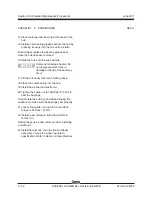
14 Place the large inner bearing into the rear of the
hub.
15 Install a new bearing grease seal into the hub by
pressing it evenly into the hub until it is flush.
Note: Always replace the bearing grease seal
when the hub has been removed.
16 Slide the hub onto the yoke spindle.
Component damage hazard. Do
not apply excessive force or
damage to the lip of the seal may
occur.
17 Fill the hub cavity with clean, fresh grease.
18 Place the outer bearing into the hub.
19 Install the washer and castle nut.
20 Tighten the castle nut to 158 ft-lbs / 214 Nm to
seat the bearings.
Note: Rotate the hub by hand while torquing the
castle nut to make sure the bearings seat properly.
21 Loosen the castle nut one full turn and then
torque to 35 ft-lbs / 47 Nm.
22 Install a new cotter pin. Bend the cotter pin
to lock it in.
Note: Always use a new cotter pin when installing
a castle nut.
23 Install the dust cap, then the tire and wheel
assembly. Torque the wheel lug nuts to
specification. Refer to Section 2,
Specifications.
Содержание Z-30/20N
Страница 1: ......
Страница 4: ...Z 30 20N Z 30 20N RJ Z 34 22 Z 34 22N PartNo 139378 June2011 iv This page intentionally left blank...
Страница 148: ...6 46 June2011 Section 6 Schematics 6 45 Power Cable Wiring Diagram...
Страница 149: ...6 47 Section 6 Schematics June2011 6 48 Drive Contactor Panel Wiring Diagram...
Страница 152: ...6 50 June2011 Section 6 Schematics Manifold and Limit Switch Wiring Diagram 6 49...
Страница 153: ...6 51 Section 6 Schematics June2011 6 52 LVI BCI Option Wiring Diagram...
Страница 156: ...6 54 June2011 Section 6 Schematics 6 53 Charger Interlock Option...
Страница 157: ...6 55 Section 6 Schematics June2011 6 56 CTE Option CE Models...
Страница 160: ...6 58 June2011 Section 6 Schematics Hydraulic Schematic 6 57...

