Part No. 139378
Z-30/20N • Z-30/20N RJ • Z-34/22 • Z-34/22N
4 - 7
June 2011
Section 4 • Repair Procedures
REV A
PLATFORM COMPONENTS
2-3
Platform Overload System
(if equipped)
How to Calibrate the Platform
Overload System
Calibration of the platform overload system is
essential to safe machine operation. Continued
use of an improperly calibrated platform overload
system could result in the system failing to sense
an overloaded platform. The stability of the
machine is compromised and it could tip over.
Note: Perform this procedure with the machine on
a firm, level surface.
1 Turn the key switch to platform control.
2 Determine the maximum platform capacity.
Refer to the machine serial plate.
3 Remove all weight, tools and accessories from
the platform.
Note: Failure to remove all weight, tools and
accessories from the platform will result in an
incorrect calibration.
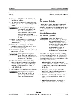
4 Using a suitable lifting device, place a test
weight equal to the maximum platform capacity
at the center of the platform floor.
5 Move the platform up and down by hand, so it
bounces approximately 2.5 to 5 cm / 1 to 2
inches. Allow the platform to settle.
Result: The overload indicator lights are off and
the alarm does not sound. Proceed to step 6.
Result: The overload indicator lights are
flashing at the platform and ground controls,
and the alarm is sounding. Slowly tighten the
load spring adjustment nut in a clockwise
direction in 10° increments until the overload
indicator light turns off, and the alarm does not
sound. Proceed to step 8.
Note: The platform will need to be moved up and
down and allowed to settle between each
adjustment.
Note: There may be a 2 second delay before the
platform overload indicator light and alarm
responds.
6 Move the platform up and down by hand, so it
bounces approximately 2.5 to 5 cm / 1 to 2
inches. Allow the platform to settle.
Result: The overload indicator lights are off at
the platform and ground controls, and the alarm
does not sound. Slowly loosen the load spring
adjustment nut in a counterclockwise direction
in 10° increments until the overload indicator
light flashes at both the platform and ground
controls, and the alarm sounds.
Proceed to step 7.
Result: The overload indicator lights are
flashing at the platform and ground controls,
and the alarm is sounding. Repeat this
procedure beginning with step 5.
Note: The platform will need to be moved up and
down and allowed to settle between each
adjustment.
Note: There may be a 2 second delay before the
platform overload indicator lights and alarm
responds.
Содержание Z-30/20N
Страница 1: ......
Страница 4: ...Z 30 20N Z 30 20N RJ Z 34 22 Z 34 22N PartNo 139378 June2011 iv This page intentionally left blank...
Страница 148: ...6 46 June2011 Section 6 Schematics 6 45 Power Cable Wiring Diagram...
Страница 149: ...6 47 Section 6 Schematics June2011 6 48 Drive Contactor Panel Wiring Diagram...
Страница 152: ...6 50 June2011 Section 6 Schematics Manifold and Limit Switch Wiring Diagram 6 49...
Страница 153: ...6 51 Section 6 Schematics June2011 6 52 LVI BCI Option Wiring Diagram...
Страница 156: ...6 54 June2011 Section 6 Schematics 6 53 Charger Interlock Option...
Страница 157: ...6 55 Section 6 Schematics June2011 6 56 CTE Option CE Models...
Страница 160: ...6 58 June2011 Section 6 Schematics Hydraulic Schematic 6 57...

