Part No. 139378
Z-30/20N • Z-30/20N RJ • Z-34/22 • Z-34/22N
4 - 27
June 2011
Section 4 • Repair Procedures
REV A
SECONDARY BOOM COMPONENTS
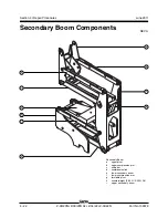
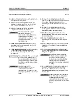
52 Attach a lifting strap from an overhead crane to
the mid-pivot for support.
53 Remove the pin retaining fasteners from the
mid-pivot to the lower secondary compression
arm pivot pins. Use a slide hammer and
remove the pins. Lower the compression arms
down.
54 Remove the pin retaining fasteners from the
mid-pivot to the lower secondary boom pivot
pin. Use a soft metal drift to remove the pins.
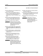
55 Remove the mid-pivot from the machine.
Crushing hazard. The mid-pivot
could become unbalanced and fall
when removed from the machine if
not properly supported by the
overhead crane.
56 Remove the secondary boom drive speed limit
switch (LS4) mounted to the turntable riser on
the ground controls side. Do not disconnect the
wiring.
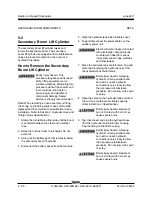
57 Attach a lifting strap from an overhead crane to
the ground control side lower secondary boom
compression arm.
58 Remove the pin retaining fastener from the
lower secondary boom compression arm to
turntable riser pivot pin.
59 Use a slide hammer and remove the pin.
Remove the compression arm from the
machine. Repeat for the hydraulic tank side
lower secondary boom compression arm.
Crushing hazard. The lower
secondary compression arm could
become unbalanced and fall when
removed from the machine if not
properly supported by the overhead
crane.
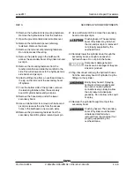
60 Attach a lifting strap from an overhead crane to
the lower secondary boom.
61 Remove the pin retaining fastener from the lower
secondary boom to turntable riser pivot pin. Use
a soft metal drift to remove the pin.
62 Remove the lower secondary boom from the
machine.
Crushing hazard. The lower
secondary boom could become
unbalanced and fall when
removed from the machine if not
properly supported by the
overhead crane.
Содержание Z-30/20N
Страница 1: ......
Страница 4: ...Z 30 20N Z 30 20N RJ Z 34 22 Z 34 22N PartNo 139378 June2011 iv This page intentionally left blank...
Страница 148: ...6 46 June2011 Section 6 Schematics 6 45 Power Cable Wiring Diagram...
Страница 149: ...6 47 Section 6 Schematics June2011 6 48 Drive Contactor Panel Wiring Diagram...
Страница 152: ...6 50 June2011 Section 6 Schematics Manifold and Limit Switch Wiring Diagram 6 49...
Страница 153: ...6 51 Section 6 Schematics June2011 6 52 LVI BCI Option Wiring Diagram...
Страница 156: ...6 54 June2011 Section 6 Schematics 6 53 Charger Interlock Option...
Страница 157: ...6 55 Section 6 Schematics June2011 6 56 CTE Option CE Models...
Страница 160: ...6 58 June2011 Section 6 Schematics Hydraulic Schematic 6 57...

