Part No. 139378
Z-30/20N • Z-30/20N RJ • Z-34/22 • Z-34/22N
4 - 37
June 2011
Section 4 • Repair Procedures
REV B
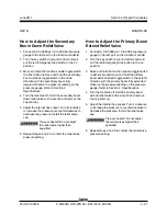
How to Adjust the Secondary
Boom Down Relief Valve
1 Connect a 0 to 3000 psi / 0 to 200 bar pressure
gauge to the test port on the function manifold.
2 Turn the key switch to ground control and pull
out the red Emergency Stop button to the on
position.
3 Move and hold the function enable toggle switch
to either side and move and hold the secondary
boom up/down toggle switch in the down
direction with the secondary boom fully
lowered. Observe the pressure reading on the
pressure gauge. Refer to Section 2,
Specifications
.
4 Turn the machine off. Hold the secondary boom
down relief valve with a wrench and remove the
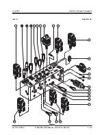
cap (item E).
5 Adjust the internal hex socket. Turn it clockwise
to increase the pressure or counterclockwise to
decrease the pressure. Install the relief valve
cap.
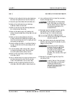
Tip-over hazard. Do not adjust
the relief valve higher than
specified.
6 Repeat steps 2 and 3 to confirm the relief valve
pressure setting.
How to Adjust the Primary Boom
Extend Relief Valve
1 Connect a 0 to 3000 psi / 0 to 200 bar pressure
gauge to the test port on the function manifold.
2 Turn the key switch to ground control and pull
out the red Emergency Stop button to the on
position.
3 Move and hold the function enable toggle switch
to either side and move and hold the primary
boom extend/retract toggle switch in the extend
direction with the primary boom fully extended.
Observe the pressure reading on the pressure
gauge. Refer to Section 2,
Specifications
.
4 Turn the machine off. Hold the primary boom
extend relief valve with a wrench and remove
the cap (item G).
5 Adjust the internal hex socket. Turn it clockwise
to increase the pressure or counterclockwise to
decrease the pressure. Install the relief valve
cap.
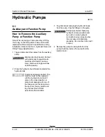
Tip-over hazard. Do not adjust
the relief valves higher than
specified.
6 Repeat steps 2 and 3 to confirm the relief valve
pressure setting.
MANIFOLDS
Содержание Z-30/20N
Страница 1: ......
Страница 4: ...Z 30 20N Z 30 20N RJ Z 34 22 Z 34 22N PartNo 139378 June2011 iv This page intentionally left blank...
Страница 148: ...6 46 June2011 Section 6 Schematics 6 45 Power Cable Wiring Diagram...
Страница 149: ...6 47 Section 6 Schematics June2011 6 48 Drive Contactor Panel Wiring Diagram...
Страница 152: ...6 50 June2011 Section 6 Schematics Manifold and Limit Switch Wiring Diagram 6 49...
Страница 153: ...6 51 Section 6 Schematics June2011 6 52 LVI BCI Option Wiring Diagram...
Страница 156: ...6 54 June2011 Section 6 Schematics 6 53 Charger Interlock Option...
Страница 157: ...6 55 Section 6 Schematics June2011 6 56 CTE Option CE Models...
Страница 160: ...6 58 June2011 Section 6 Schematics Hydraulic Schematic 6 57...


