


Part No. 1268494
S-100 • S-105 • S-120 • S-125
3 - 47
March 2017
Section 3 • Repair Procedures
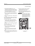
BOOM COMPONENTS
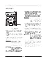
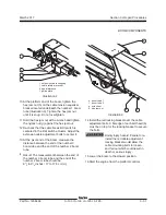
8
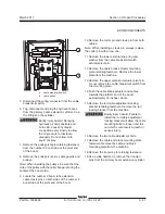
S-120 and S-125 models:
Remove the
fasteners from the inner cable track mounting
bracket at the primary boom extension cylinder.
9
S-120 and S-125 models:
Lay the inner cable
track and hoses down and out of the way.
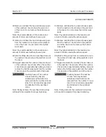
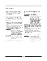
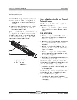
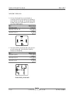
10 Remove the pulley pivot pin retaining fasteners
from the number 2 boom tube at the pivot end
of the boom.
11 Remove the pulley pivot pins, cable guards and
pulleys.
Note: When installing the pulleys, be sure that the
side of the pulley with the shorter flange is facing
the inside of the boom tube.
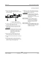
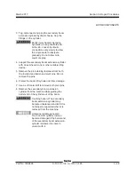
12 Locate the number 3 boom tube extension
cable clevis pins on both sides of the number 2
boom tube at the pivot end of the boom.
13 Remove the cotter pin and clevis pin from both
cables.
Note: When installing a clevis pin, always replace
the cotter pin with a new one.
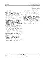
14 Remove the lower external snap ring and
washer from the cable break limit switch
actuator pivot pin.
15 Remove the cable break actuator mounting
plate retaining fasteners. Remove the lower
plate.
16 Remove the upper plate and actuator pivot pin.
Do not remove the cable break limit switch from
the mounting plate.
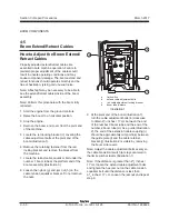
17 Push the cable break actuator and cables
towards the platform end of the boom
approximately 18 inches / 46 cm.
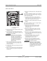
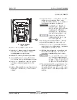
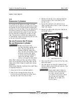
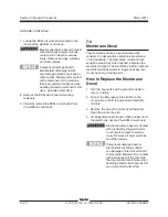
18 Remove the retaining fasteners from the red
cable adjustment locking bracket. Remove the
red locking bracket.
Bodily injury hazard. Failure to
install the red cable adjustment
locking bracket would allow the
cable mounting bolts to loosen
and fall out which could result in
death or serious injury.
a
red cable adjustment
locking bracket
a
Содержание S-100
Страница 224: ...4 38 S 100 S 105 S 120 S 125 Part No 1268494 March 2017 Section 4 Diagnostic Codes This page intentionally left blank ...
Страница 244: ...March 2017 Section 5 Schematics 5 20 S 100 S 105 S 120 S 125 Part No 1268494 This page intentionally left blank ...
Страница 246: ...March 2017 Section 6 Schematics 6 22 Safety Circuit Schematic 6 21 ...
Страница 253: ...Section 6 Schematics March 2017 6 29 Engine Options Perkins S 100 105 120 125 from serial number 874 6 30 ...
Страница 259: ...Section 6 Schematics March 2017 6 35 6 36 Electrical Schematic Generator Options ...
Страница 262: ...March 2017 Section 6 Schematics 6 38 6 37 Electrical Schematic 12 kW Generator welder option ...
Страница 264: ...March 2017 Section 6 Schematics 6 40 Perkins 1104D 44T Engine Electrical Schematic 6 39 ...
Страница 265: ...Section 6 Schematics March 2017 6 41 Perkins 854F 34T Engine Electrical Schematic 6 42 ...
Страница 267: ...Part No 1268494 S 100 S 105 S 120 S 125 6 43 March 2017 Section 6 Schematics Perkins 854F 34T Engine Electrical Harness ...
Страница 268: ...March 2017 Section 6 Schematics 6 44 Perkins 854F 34T Engine Harness 6 45 ...
Страница 269: ...Section 6 Schematics March 2017 6 45 Deutz TD2011L04i Engine Electrical Schematic 6 46 ...
Страница 271: ...Section 6 Schematics March 2017 6 47 Deutz TD2 9 Engine Electrical Schematic 6 48 ...
Страница 272: ...6 48 S 100 S 105 S 120 S 125 Part No 1268494 March 2017 Section 6 Schematics Deutz TD2 9 Engine Electrical Schematic ...
Страница 273: ...Part No 1268494 S 100 S 105 S 120 S 125 6 49 March 2017 Section 6 Schematics Deutz TD2 9 Engine Electrical Harness ...
Страница 274: ...March 2017 Section 6 Schematics 6 50 Deutz TD2 9 Engine Electrical Harness 6 51 ...
Страница 276: ...March 2017 Section 6 Schematics 6 52 6 53 Hydraulic Schematic 12 kW Generator welder option ...
Страница 277: ...Section 6 Schematics March 2017 6 53 Hydraulic Schematic S 100 S 105 Models serial number 136 6 54 ...
Страница 284: ...March 2017 Section 6 Schematics 6 60 Hydraulic Schematic S 100 S 105 Models from serial number 739 6 61 ...
Страница 293: ...Section 6 Schematics March 2017 6 69 Hydraulic Schematic S 120 S 125 Models from serial number 3146 to S12514D 921 6 70 ...
Страница 296: ...March 2017 Section 6 Schematics 6 72 Hydraulic Schematic S 120 S 125 Models from serial number S12514D 922 6 73 ...


