


Part No. 1268494
S-100 • S-105 • S-120 • S-125
3 - 11
March 2017
Section 3 • Repair Procedures
Primary boom extend/retract functions:
Note: If the calibration fault is already displayed at
the ground box begin with step 6.
1 Turn the key switch to the off position. Confirm
the red Emergency Stop button at the platform
and ground controls is in the on position.
2 Press and hold the enter button
on the
ground control panel while turning the key
switch to platform controls. Hold the enter
button for approximately 5 seconds.
3 Press the minus button
twice, then press the
enter button
twice.
4 Use the scroll button to scroll through the
menu until
reset
primary
boom
extend
/
retract
joystick
defaults
is displayed. Press the
button to select
yes
, then press the
button.
5 Exit programming mode.
Note: To exit programming mode, use the scroll
button to scroll through the menu until the
screen displays exit, then press the plus button
once, change the NO to YES, and press the enter
button
.
6 Do not start the engine.
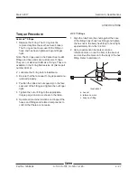
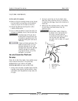
7 Locate the primary boom/turntable rotate
joystick.
8 Move the primary boom extend/retract joystick
full stroke in the extend direction and hold for
5 seconds, then return to the center or neutral
position.
9 Move the primary boom extend/retract joystick
full stroke in the retract direction and hold for
5 seconds, then return to the center or neutral
position.
Result: The alarm at the ground controls should
sound for a successful calibration.
Result: If the alarm does not sound, repeat the
calibration procedure, beginning with step 1.
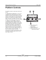
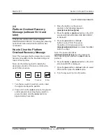
PLATFORM CONTROLS
REV B
Primary boom up/down functions:
Note: If the calibration fault is already displayed at
the ground box begin with step 6.
1 Turn the key switch to the off position. Confirm
the red Emergency Stop button at the platform
and ground controls is in the on position.
2 Press and hold the enter button
on the
ground control panel while turning the key
switch to platform controls. Hold the enter
button for approximately 5 seconds.
3 Press the minus button
twice, then press the
enter button
twice.
4 Use the scroll button to scroll through the
menu until
reset
primary
boom
up
/
down
joystick
defaults
is displayed. Press the
button to
select
yes
, then press the
button.
5 Exit programming mode.
Note: To exit programming mode, use the scroll
button to scroll through the menu until the
screen displays exit, then press the plus button
once, change the NO to YES, and press the enter
button
.
6 Do not start the engine.
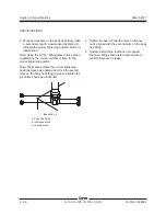
7 Locate the primary boom/turntable rotate
joystick.
8 Move the boom/turntable rotate joystick
full stroke in the up direction and hold for 5
seconds, then return to the center or neutral
position.
9 Move the boom/turntable rotate joystick full
stroke in the down direction and hold for 5
seconds, then return to the center or neutral
position.
Result: The alarm at the ground controls should
sound for a successful calibration.
Result: If the alarm does not sound, repeat the
calibration procedure, beginning with step 1.
Содержание S-100
Страница 224: ...4 38 S 100 S 105 S 120 S 125 Part No 1268494 March 2017 Section 4 Diagnostic Codes This page intentionally left blank ...
Страница 244: ...March 2017 Section 5 Schematics 5 20 S 100 S 105 S 120 S 125 Part No 1268494 This page intentionally left blank ...
Страница 246: ...March 2017 Section 6 Schematics 6 22 Safety Circuit Schematic 6 21 ...
Страница 253: ...Section 6 Schematics March 2017 6 29 Engine Options Perkins S 100 105 120 125 from serial number 874 6 30 ...
Страница 259: ...Section 6 Schematics March 2017 6 35 6 36 Electrical Schematic Generator Options ...
Страница 262: ...March 2017 Section 6 Schematics 6 38 6 37 Electrical Schematic 12 kW Generator welder option ...
Страница 264: ...March 2017 Section 6 Schematics 6 40 Perkins 1104D 44T Engine Electrical Schematic 6 39 ...
Страница 265: ...Section 6 Schematics March 2017 6 41 Perkins 854F 34T Engine Electrical Schematic 6 42 ...
Страница 267: ...Part No 1268494 S 100 S 105 S 120 S 125 6 43 March 2017 Section 6 Schematics Perkins 854F 34T Engine Electrical Harness ...
Страница 268: ...March 2017 Section 6 Schematics 6 44 Perkins 854F 34T Engine Harness 6 45 ...
Страница 269: ...Section 6 Schematics March 2017 6 45 Deutz TD2011L04i Engine Electrical Schematic 6 46 ...
Страница 271: ...Section 6 Schematics March 2017 6 47 Deutz TD2 9 Engine Electrical Schematic 6 48 ...
Страница 272: ...6 48 S 100 S 105 S 120 S 125 Part No 1268494 March 2017 Section 6 Schematics Deutz TD2 9 Engine Electrical Schematic ...
Страница 273: ...Part No 1268494 S 100 S 105 S 120 S 125 6 49 March 2017 Section 6 Schematics Deutz TD2 9 Engine Electrical Harness ...
Страница 274: ...March 2017 Section 6 Schematics 6 50 Deutz TD2 9 Engine Electrical Harness 6 51 ...
Страница 276: ...March 2017 Section 6 Schematics 6 52 6 53 Hydraulic Schematic 12 kW Generator welder option ...
Страница 277: ...Section 6 Schematics March 2017 6 53 Hydraulic Schematic S 100 S 105 Models serial number 136 6 54 ...
Страница 284: ...March 2017 Section 6 Schematics 6 60 Hydraulic Schematic S 100 S 105 Models from serial number 739 6 61 ...
Страница 293: ...Section 6 Schematics March 2017 6 69 Hydraulic Schematic S 120 S 125 Models from serial number 3146 to S12514D 921 6 70 ...
Страница 296: ...March 2017 Section 6 Schematics 6 72 Hydraulic Schematic S 120 S 125 Models from serial number S12514D 922 6 73 ...


