


Part No. 1268494
S-100 • S-105 • S-120 • S-125
3 - 39
March 2017
Section 3 • Repair Procedures
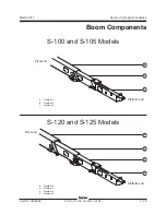
BOOM COMPONENTS
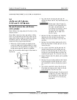
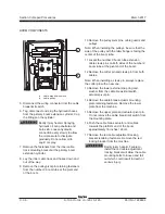
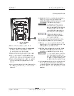
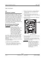
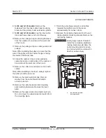
39 Support and slide the number 2 boom tube out
of the number 1 boom tube. When the number
2 boom tube is approximately halfway removed,
remove the bottom wear pads from the number
1 boom tube at the platform end of the boom.
Crushing hazard. The number
2 boom tube may become
unbalanced and fall when it is
removed from the number 1 boom
tube if it is not properly supported
and attached to the overhead
crane.
Note: During removal, the overhead crane strap
will need to be adjusted for proper balancing.
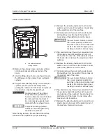
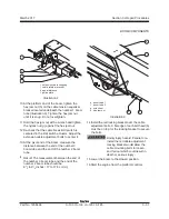
40 Remove the secondary boom extend cylinder
cover retaining fasteners. Remove the covers.
Bodily injury hazard. Do not
operate the machine unless the
secondary extend cylinder covers
are properly installed. Operating
the machine with the covers
removed could result in death or
serious injury.
41 Tag, disconnect and plug the secondary boom
extension cylinder hydraulic hoses. Cap the
fittings on the cylinder.
Bodily injury hazard. Spraying
hydraulic oil can penetrate and
burn skin. Loosen hydraulic
connections very slowly to allow
the oil pressure to dissipate
gradually. Do not allow oil to
squirt or spray.
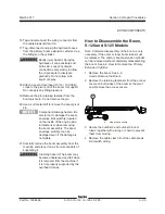
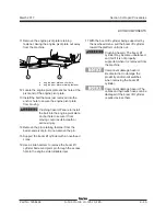
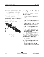
42 Support the secondary boom extension cylinder
with an overhead crane or other suitable lifting
device.
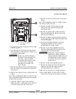
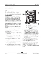
43 Remove the pin retaining fasteners from both
the rod-end and barrel-end pivot pins. Do not
remove the pins.
44 Use a soft metal drift to remove both pivot pins
and remove the secondary boom extension
cylinder from the machine while guiding the
barrel end of the cylinder out of the boom.
Crushing hazard. The secondary
boom extension cylinder may
become unbalanced and fall if it is
not properly supported when it is
removed from the machine.
Component damage hazard.
The boom lift cylinder rod can
become damaged if the barrel end
of the secondary boom extension
cylinder is allowed to come in
contact with it.
45 Remove and label the top and side wear pads
from the number 1 boom tube at the pivot end
of the boom. Do not remove the bottom wear
pads.
Note: Pay careful attention to the location and
amount of shims used with each wear pad.
Содержание S-100
Страница 224: ...4 38 S 100 S 105 S 120 S 125 Part No 1268494 March 2017 Section 4 Diagnostic Codes This page intentionally left blank ...
Страница 244: ...March 2017 Section 5 Schematics 5 20 S 100 S 105 S 120 S 125 Part No 1268494 This page intentionally left blank ...
Страница 246: ...March 2017 Section 6 Schematics 6 22 Safety Circuit Schematic 6 21 ...
Страница 253: ...Section 6 Schematics March 2017 6 29 Engine Options Perkins S 100 105 120 125 from serial number 874 6 30 ...
Страница 259: ...Section 6 Schematics March 2017 6 35 6 36 Electrical Schematic Generator Options ...
Страница 262: ...March 2017 Section 6 Schematics 6 38 6 37 Electrical Schematic 12 kW Generator welder option ...
Страница 264: ...March 2017 Section 6 Schematics 6 40 Perkins 1104D 44T Engine Electrical Schematic 6 39 ...
Страница 265: ...Section 6 Schematics March 2017 6 41 Perkins 854F 34T Engine Electrical Schematic 6 42 ...
Страница 267: ...Part No 1268494 S 100 S 105 S 120 S 125 6 43 March 2017 Section 6 Schematics Perkins 854F 34T Engine Electrical Harness ...
Страница 268: ...March 2017 Section 6 Schematics 6 44 Perkins 854F 34T Engine Harness 6 45 ...
Страница 269: ...Section 6 Schematics March 2017 6 45 Deutz TD2011L04i Engine Electrical Schematic 6 46 ...
Страница 271: ...Section 6 Schematics March 2017 6 47 Deutz TD2 9 Engine Electrical Schematic 6 48 ...
Страница 272: ...6 48 S 100 S 105 S 120 S 125 Part No 1268494 March 2017 Section 6 Schematics Deutz TD2 9 Engine Electrical Schematic ...
Страница 273: ...Part No 1268494 S 100 S 105 S 120 S 125 6 49 March 2017 Section 6 Schematics Deutz TD2 9 Engine Electrical Harness ...
Страница 274: ...March 2017 Section 6 Schematics 6 50 Deutz TD2 9 Engine Electrical Harness 6 51 ...
Страница 276: ...March 2017 Section 6 Schematics 6 52 6 53 Hydraulic Schematic 12 kW Generator welder option ...
Страница 277: ...Section 6 Schematics March 2017 6 53 Hydraulic Schematic S 100 S 105 Models serial number 136 6 54 ...
Страница 284: ...March 2017 Section 6 Schematics 6 60 Hydraulic Schematic S 100 S 105 Models from serial number 739 6 61 ...
Страница 293: ...Section 6 Schematics March 2017 6 69 Hydraulic Schematic S 120 S 125 Models from serial number 3146 to S12514D 921 6 70 ...
Страница 296: ...March 2017 Section 6 Schematics 6 72 Hydraulic Schematic S 120 S 125 Models from serial number S12514D 922 6 73 ...


