


3 - 56
S-100 • S-105 • S-120 • S-125
Part No. 1268494
March 2017
Section 3 • Repair Procedures
6-1
RPM Adjustment
Refer to Maintenance Procedure,
Check and Adjust the Engine RPM.
6-2
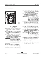
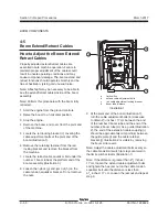
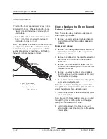
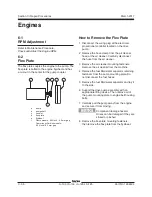
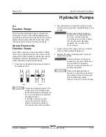
Flex Plate
The flex plate couples the engine to the pump. The
flex plate is bolted to the engine flywheel and has
a cut-out in the center for the pump coupler.
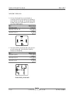
a pump
b
pump shaft
c coupler
d
flex plate
e
flywheel
f
Deutz models- .245
inch / 6.2 mm gap
Cummins or Perkins models-
.255 inch / 6.5 mm gap
Engines
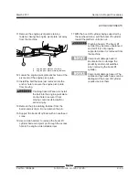
How to Remove the Flex Plate
1 Disconnect the wiring plug at the electronic
proportional controller located on the drive
pump.
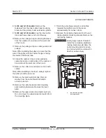
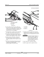
2 Remove the hose clamp from the air cleaner
hose at the air cleaner. Carefully disconnect
the hose from the air cleaner.
3 Remove the air cleaner mounting fasteners.
Remove the air cleaner from the machine.
4 Remove the fuel filter/water separator retaining
fasteners from the pump mounting plate. Do
not disconnect the fuel hoses.
5 Remove the fuel filter/water separator and lay it
to the side.
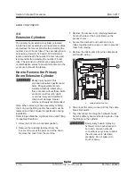
6 Support the drive pump assembly with an
appropriate lifting device. Then remove all of
the pump mounting plate to engine bell housing
bolts.
7 Carefully pull the pump away from the engine
and secure it from moving.
Component damage hazard.
Hoses can be damaged if they are
kinked or pinched.
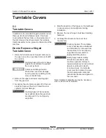
8 Remove the flex plate mounting fasteners,
then remove the flex plate from the flywheel.
a
b
c
e
f
d
Содержание S-100
Страница 224: ...4 38 S 100 S 105 S 120 S 125 Part No 1268494 March 2017 Section 4 Diagnostic Codes This page intentionally left blank ...
Страница 244: ...March 2017 Section 5 Schematics 5 20 S 100 S 105 S 120 S 125 Part No 1268494 This page intentionally left blank ...
Страница 246: ...March 2017 Section 6 Schematics 6 22 Safety Circuit Schematic 6 21 ...
Страница 253: ...Section 6 Schematics March 2017 6 29 Engine Options Perkins S 100 105 120 125 from serial number 874 6 30 ...
Страница 259: ...Section 6 Schematics March 2017 6 35 6 36 Electrical Schematic Generator Options ...
Страница 262: ...March 2017 Section 6 Schematics 6 38 6 37 Electrical Schematic 12 kW Generator welder option ...
Страница 264: ...March 2017 Section 6 Schematics 6 40 Perkins 1104D 44T Engine Electrical Schematic 6 39 ...
Страница 265: ...Section 6 Schematics March 2017 6 41 Perkins 854F 34T Engine Electrical Schematic 6 42 ...
Страница 267: ...Part No 1268494 S 100 S 105 S 120 S 125 6 43 March 2017 Section 6 Schematics Perkins 854F 34T Engine Electrical Harness ...
Страница 268: ...March 2017 Section 6 Schematics 6 44 Perkins 854F 34T Engine Harness 6 45 ...
Страница 269: ...Section 6 Schematics March 2017 6 45 Deutz TD2011L04i Engine Electrical Schematic 6 46 ...
Страница 271: ...Section 6 Schematics March 2017 6 47 Deutz TD2 9 Engine Electrical Schematic 6 48 ...
Страница 272: ...6 48 S 100 S 105 S 120 S 125 Part No 1268494 March 2017 Section 6 Schematics Deutz TD2 9 Engine Electrical Schematic ...
Страница 273: ...Part No 1268494 S 100 S 105 S 120 S 125 6 49 March 2017 Section 6 Schematics Deutz TD2 9 Engine Electrical Harness ...
Страница 274: ...March 2017 Section 6 Schematics 6 50 Deutz TD2 9 Engine Electrical Harness 6 51 ...
Страница 276: ...March 2017 Section 6 Schematics 6 52 6 53 Hydraulic Schematic 12 kW Generator welder option ...
Страница 277: ...Section 6 Schematics March 2017 6 53 Hydraulic Schematic S 100 S 105 Models serial number 136 6 54 ...
Страница 284: ...March 2017 Section 6 Schematics 6 60 Hydraulic Schematic S 100 S 105 Models from serial number 739 6 61 ...
Страница 293: ...Section 6 Schematics March 2017 6 69 Hydraulic Schematic S 120 S 125 Models from serial number 3146 to S12514D 921 6 70 ...
Страница 296: ...March 2017 Section 6 Schematics 6 72 Hydraulic Schematic S 120 S 125 Models from serial number S12514D 922 6 73 ...


