


3 - 72
S-100 • S-105 • S-120 • S-125
Part No. 1268494
March 2017
Section 3 • Repair Procedures
9-2
Drive Pump
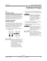
The drive pump is a bi-directional variable
displacement piston pump. The pump output is
controlled by the electronic displacement controller
(EDC), located on the pump. The only adjustment
that can be made to the pump is the neutral
or null adjustment. Any internal service to the
pump should only be performed at an authorized
Sundstrand-Sauer service center. Call the Genie
Industries Service Department to locate your local
authorized service center.
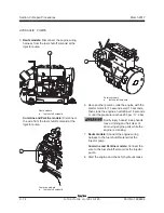
How to Remove the Drive Pump
Component damage hazard. The
work area and surfaces where this
procedure will be performed must
be clean and free of debris that
could get into the hydraulic system
and cause severe component
damage. Dealer service is
recommended.
Note: When removing a hose assembly or fitting,
the O-ring on the fitting and/or hose end must be
replaced and then torqued to specification during
installation. Refer to Specifications,
Hydraulic
Hose and Fitting Torque Specifications.
1 Remove the function pumps. See
How to
Remove the Function Pumps.
2 Disconnect the electrical connection at the
electronic displacement controller (EDC)
located on the drive pump.
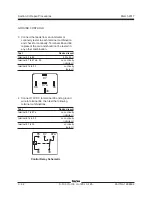
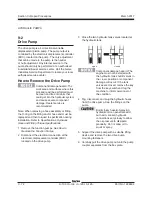
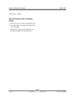
3 Close the two hydraulic tank valves located at
the hydraulic tank.
Component damage hazard. The
engine must not be started with
the hydraulic tank shutoff valves in
the
closed
position or component
damage will occur. If the tank
valves are closed, remove the key
from the key switch and tag the
machine to inform personnel of
the condition.
4 Tag, disconnect and plug the hydraulic hoses
from the drive pump. Cap the fittings on the
pump.
Bodily injury hazard. Spraying
hydraulic oil can penetrate and
burn skin. Loosen hydraulic
connections very slowly to allow
the oil pressure to dissipate
gradually. Do not allow oil to
squirt or spray.
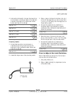
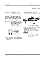
5 Support the drive pump with a suitable lifting
device and remove the two drive pump
mounting fasteners.
6 Carefully pull the drive pump out until the pump
coupler separates from the flex plate.
open closed
HYDRAULIC PUMPS
Содержание S-100
Страница 224: ...4 38 S 100 S 105 S 120 S 125 Part No 1268494 March 2017 Section 4 Diagnostic Codes This page intentionally left blank ...
Страница 244: ...March 2017 Section 5 Schematics 5 20 S 100 S 105 S 120 S 125 Part No 1268494 This page intentionally left blank ...
Страница 246: ...March 2017 Section 6 Schematics 6 22 Safety Circuit Schematic 6 21 ...
Страница 253: ...Section 6 Schematics March 2017 6 29 Engine Options Perkins S 100 105 120 125 from serial number 874 6 30 ...
Страница 259: ...Section 6 Schematics March 2017 6 35 6 36 Electrical Schematic Generator Options ...
Страница 262: ...March 2017 Section 6 Schematics 6 38 6 37 Electrical Schematic 12 kW Generator welder option ...
Страница 264: ...March 2017 Section 6 Schematics 6 40 Perkins 1104D 44T Engine Electrical Schematic 6 39 ...
Страница 265: ...Section 6 Schematics March 2017 6 41 Perkins 854F 34T Engine Electrical Schematic 6 42 ...
Страница 267: ...Part No 1268494 S 100 S 105 S 120 S 125 6 43 March 2017 Section 6 Schematics Perkins 854F 34T Engine Electrical Harness ...
Страница 268: ...March 2017 Section 6 Schematics 6 44 Perkins 854F 34T Engine Harness 6 45 ...
Страница 269: ...Section 6 Schematics March 2017 6 45 Deutz TD2011L04i Engine Electrical Schematic 6 46 ...
Страница 271: ...Section 6 Schematics March 2017 6 47 Deutz TD2 9 Engine Electrical Schematic 6 48 ...
Страница 272: ...6 48 S 100 S 105 S 120 S 125 Part No 1268494 March 2017 Section 6 Schematics Deutz TD2 9 Engine Electrical Schematic ...
Страница 273: ...Part No 1268494 S 100 S 105 S 120 S 125 6 49 March 2017 Section 6 Schematics Deutz TD2 9 Engine Electrical Harness ...
Страница 274: ...March 2017 Section 6 Schematics 6 50 Deutz TD2 9 Engine Electrical Harness 6 51 ...
Страница 276: ...March 2017 Section 6 Schematics 6 52 6 53 Hydraulic Schematic 12 kW Generator welder option ...
Страница 277: ...Section 6 Schematics March 2017 6 53 Hydraulic Schematic S 100 S 105 Models serial number 136 6 54 ...
Страница 284: ...March 2017 Section 6 Schematics 6 60 Hydraulic Schematic S 100 S 105 Models from serial number 739 6 61 ...
Страница 293: ...Section 6 Schematics March 2017 6 69 Hydraulic Schematic S 120 S 125 Models from serial number 3146 to S12514D 921 6 70 ...
Страница 296: ...March 2017 Section 6 Schematics 6 72 Hydraulic Schematic S 120 S 125 Models from serial number S12514D 922 6 73 ...


