


3 - 40
S-100 • S-105 • S-120 • S-125
Part No. 1268494
March 2017
Section 3 • Repair Procedures
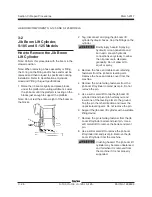
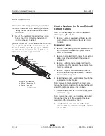
46 Remove and label the top and side wear pads
from the number 0 boom tube at the platform
end of the boom. Do not remove the bottom
wear pads.
Note: Pay careful attention to the location and
amount of shims used with each wear pad.
47 Attach a lifting strap from an overhead crane to
the number 1 boom tube at the platform end of
the boom.
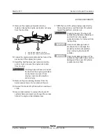
48 Support and slide the number 1 boom tube out
of the number 0 boom tube. When the number
1 boom tube is approximately halfway removed,
remove the bottom wear pads from the number
0 boom tube at the platform end of the boom.
Crushing hazard. The number
1 boom tube may become
unbalanced and fall when it is
removed from the number 0 boom
tube if it is not properly supported
and attached to the overhead
crane.
Note: During removal, the overhead crane strap
will need to be adjusted for proper balancing.
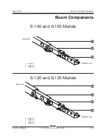
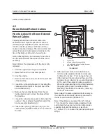
BOOM COMPONENTS
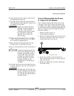
How to Disassemble the Boom,
S-100 and S-105 Models
Note: Complete disassembly of the boom is only
necessary
if the outer or inner boom tubes must be replaced.
The primary boom extension cylinder can be
removed without completely disassembling the
boom. See 4-4,
How to Remove the Primary
Extension Cylinder
.
1 Remove the boom. See 4-2,
How to Remove the Boom
.
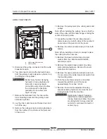
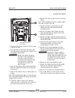
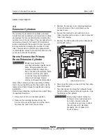
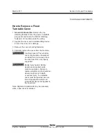
2 Remove the retaining fasteners from the access
covers on both sides of the boom at the pivot
end. Remove the access covers.
a
side access covers
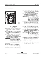
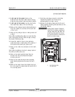
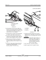
3 Secure the number 2 and number 3 boom
tubes together with a strap or chain to prevent
them from moving.
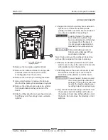
4 Remove the cable clamp from the cable break
limit switch wiring.
a
Содержание S-100
Страница 224: ...4 38 S 100 S 105 S 120 S 125 Part No 1268494 March 2017 Section 4 Diagnostic Codes This page intentionally left blank ...
Страница 244: ...March 2017 Section 5 Schematics 5 20 S 100 S 105 S 120 S 125 Part No 1268494 This page intentionally left blank ...
Страница 246: ...March 2017 Section 6 Schematics 6 22 Safety Circuit Schematic 6 21 ...
Страница 253: ...Section 6 Schematics March 2017 6 29 Engine Options Perkins S 100 105 120 125 from serial number 874 6 30 ...
Страница 259: ...Section 6 Schematics March 2017 6 35 6 36 Electrical Schematic Generator Options ...
Страница 262: ...March 2017 Section 6 Schematics 6 38 6 37 Electrical Schematic 12 kW Generator welder option ...
Страница 264: ...March 2017 Section 6 Schematics 6 40 Perkins 1104D 44T Engine Electrical Schematic 6 39 ...
Страница 265: ...Section 6 Schematics March 2017 6 41 Perkins 854F 34T Engine Electrical Schematic 6 42 ...
Страница 267: ...Part No 1268494 S 100 S 105 S 120 S 125 6 43 March 2017 Section 6 Schematics Perkins 854F 34T Engine Electrical Harness ...
Страница 268: ...March 2017 Section 6 Schematics 6 44 Perkins 854F 34T Engine Harness 6 45 ...
Страница 269: ...Section 6 Schematics March 2017 6 45 Deutz TD2011L04i Engine Electrical Schematic 6 46 ...
Страница 271: ...Section 6 Schematics March 2017 6 47 Deutz TD2 9 Engine Electrical Schematic 6 48 ...
Страница 272: ...6 48 S 100 S 105 S 120 S 125 Part No 1268494 March 2017 Section 6 Schematics Deutz TD2 9 Engine Electrical Schematic ...
Страница 273: ...Part No 1268494 S 100 S 105 S 120 S 125 6 49 March 2017 Section 6 Schematics Deutz TD2 9 Engine Electrical Harness ...
Страница 274: ...March 2017 Section 6 Schematics 6 50 Deutz TD2 9 Engine Electrical Harness 6 51 ...
Страница 276: ...March 2017 Section 6 Schematics 6 52 6 53 Hydraulic Schematic 12 kW Generator welder option ...
Страница 277: ...Section 6 Schematics March 2017 6 53 Hydraulic Schematic S 100 S 105 Models serial number 136 6 54 ...
Страница 284: ...March 2017 Section 6 Schematics 6 60 Hydraulic Schematic S 100 S 105 Models from serial number 739 6 61 ...
Страница 293: ...Section 6 Schematics March 2017 6 69 Hydraulic Schematic S 120 S 125 Models from serial number 3146 to S12514D 921 6 70 ...
Страница 296: ...March 2017 Section 6 Schematics 6 72 Hydraulic Schematic S 120 S 125 Models from serial number S12514D 922 6 73 ...


