—————— TPD32-EV ——————
80
4.7 DIGITAL ENCODER INTERFACE DEII
4.7.1 Description
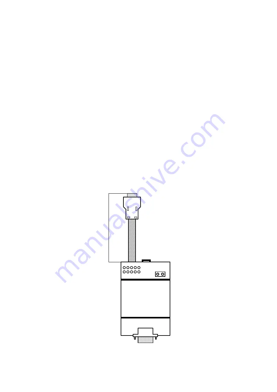
The option card DEII has been projected to adapt, to separate galvanically and to connect a digital encoder to
the input XE1 of the converters TPD32-EV regulations boards. As standard, this input is arranged for the con
-
nection of an analog encoder.
The card DEII will be fixed externally to the drive by the mounting rail DIN EN 50 022-35. The input female
connector
XS1
must be connected to the digital encoder using a 9-pole male connector, through a shielded cable,
Tasker c/186 (6 x 2 x 0.22) with a maximal length of 150 m.
Male output connector XS2 with 1.5 m shielded cable must be connected to the 9-pin connector fitted on the
TPD32-EV control card. The input voltage can be 15V...24V (HTL) or 5V (TTL), depending on whether the
encoder to be connected is type HTL or TTL. When the voltage connected to terVenc and 0Venc is
switched on, the HTL or TTL LED will light up. If the encoder has HTL outputs, switch S1-S2-S3 must be
positioned on HTL side (default configuration); on the opposite side if the encoder has a TTL output. If switch
S1-S2-S3 is positioned on TTL side, vVenc is also connected to pin 9 of XS1, in addition to pin 2.
S4 jumper is used to cut out the channel C (no impulse) from the test of encoder loss. S4 closed = canal C in
-
cluded, S4 open = canal C cut out. The EL LED lights up to signal the absence of at least one encoder signal.
The function that checks the absence of encoder signals works correctly only with encoders with complementary
outputs. It does NOT work with single-ended encoder drivers.
The jumper SH is mounted on condition of standard delivery; it must be cut only in case of the shield side en
-
coder is connected to the chassis of the motor, to avoid the forming a ground ring.
For converter operation with the DEII card it is necessary to set the jumper S5, S6 on the regulation board in
position A.
1
3
5
7
9
4
2
6
8
SH
XS1
+V
enc
0V
enc
Cable
Lengt
h
=
1.5m
DEII
XS2
Figure 4.7.1.1: DEII card
Содержание TPD32-EV-...-2B
Страница 1: ... Instruction manual Industrial Application DC drives TPD32 EV ...
Страница 62: ... TPD32 EV 62 10 mm 0 4 150 mm 6 150 mm 6 150 mm 6 10 mm 0 4 10 mm 0 4 50 mm 2 Figure 3 3 2 Mounting Clearance ...
Страница 372: ... TPD32 EV 372 9 BLOCK DIAGRAM 9 1 CONTROL BLOCK DIAGRAMS ...
Страница 373: ... Instruction manual 373 ...
Страница 374: ... TPD32 EV 374 ...
Страница 375: ... Instruction manual 375 ...
Страница 376: ... TPD32 EV 376 ...
Страница 377: ... Instruction manual 377 ...
Страница 378: ... TPD32 EV 378 ...
Страница 379: ... Instruction manual 379 ...
Страница 380: ... TPD32 EV 380 ...
Страница 381: ... Instruction manual 381 ...
Страница 382: ... TPD32 EV 382 ...
Страница 383: ... Instruction manual 383 ...
Страница 384: ... TPD32 EV 384 ...
Страница 385: ... Instruction manual 385 ...
Страница 386: ... TPD32 EV 386 ...
Страница 387: ... Instruction manual 387 ...
Страница 388: ... TPD32 EV 388 ...
Страница 389: ... Instruction manual 389 ...
Страница 390: ... TPD32 EV 390 ...
Страница 391: ... Instruction manual 391 ...
Страница 392: ... TPD32 EV 392 ...
Страница 393: ... Instruction manual 393 ...
Страница 394: ... TPD32 EV 394 ...
Страница 395: ... Instruction manual 395 ...
Страница 396: ... TPD32 EV 396 ...
Страница 397: ... Instruction manual 397 ...
Страница 398: ... TPD32 EV 398 ...
Страница 399: ... Instruction manual 399 ...
Страница 400: ... TPD32 EV 400 ...
Страница 401: ... Instruction manual 401 ...
Страница 402: ... TPD32 EV 402 ...
Страница 501: ... Instruction manual 501 APPENDIX 3 ACCESSORIES A3 1 EAM Adapter Kit EAM1579 EAM1580 ...
Страница 503: ......


