


—————— TPD32-EV ——————
130
Voltage regulator in the field converter
n
ote
!
In the most of the cases the DC motors with an independent excitation operate with a direct
field (
Flux reg mode=Constant current
). In this case it is not necessary to optimize the
regulator of the armature voltage.
When a Voltage control occurs, the voltage regulator keeps the armature voltage at a constant level. The most
difficult moment for this regulator is the beginning of the Voltage control, because due to the saturation of the
motor field, the flux variation requires quicker changes of the field current.
Tune the regulator in order to have small changes of the armature voltage.
n
ote
!
All the other converter regulators must be set before the optimization of the voltage regulator.
- Drive disabled = no voltage on terminal 12
- Choose the following settings for the Test generator :
-
Gen access
=
Ramp ref
-
Gen frequency
=
0.2 Hz
-
Gen amplitude
=
10 %
-
Gen offset
=
according to the changing point from the armature regulation
to the field one. Example:
Motor max speed
= 2000 rpm,
the Voltage control starts at 1500 rpm.
Gen offset
= 75 %
- Measure the field current and the armature voltage on an analog output. The “Flux current” and the “Output
voltage” variables must be set on two different analog outputs (see Programming “Inputs/Outputs).
- Enable the drive and give the Start command (voltage on the terminals 12 and 13)
- Check the armature voltage. After a possible short jump, the voltage should remain constant. See figures
5.3.6.8 ... 5.3.6.10. In the REG PARAMETER /... menu, it is possible to change the P and I section with
the
Voltage P
and
Voltage I
parameters.
- Stop and disable the drive.
- Gen access = Not connected
- Save the settings.
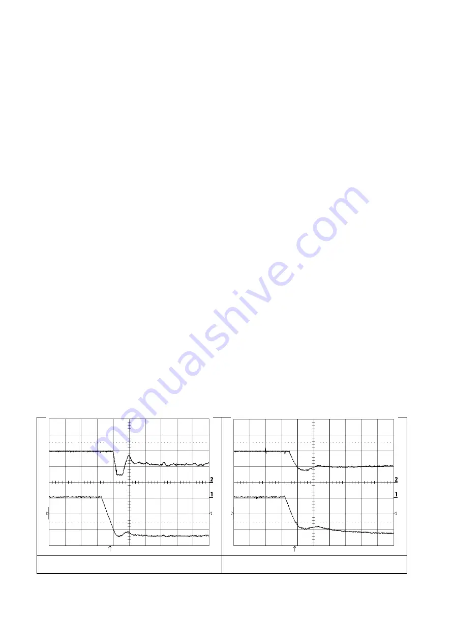
Figure 5.3.6.8: Above: Flux; Below: Output voltage. After a speed change the
field current (Flux) has some jumps. Voltage P = 10%, Voltage I = 80%.
Figure 5.3.6.9: Above: Flux; Below: Output voltage. The gain is too low. The
armature voltage increases. Voltage P = 3%, Voltage I = 5%.
Содержание TPD32-EV-...-2B
Страница 1: ... Instruction manual Industrial Application DC drives TPD32 EV ...
Страница 62: ... TPD32 EV 62 10 mm 0 4 150 mm 6 150 mm 6 150 mm 6 10 mm 0 4 10 mm 0 4 50 mm 2 Figure 3 3 2 Mounting Clearance ...
Страница 372: ... TPD32 EV 372 9 BLOCK DIAGRAM 9 1 CONTROL BLOCK DIAGRAMS ...
Страница 373: ... Instruction manual 373 ...
Страница 374: ... TPD32 EV 374 ...
Страница 375: ... Instruction manual 375 ...
Страница 376: ... TPD32 EV 376 ...
Страница 377: ... Instruction manual 377 ...
Страница 378: ... TPD32 EV 378 ...
Страница 379: ... Instruction manual 379 ...
Страница 380: ... TPD32 EV 380 ...
Страница 381: ... Instruction manual 381 ...
Страница 382: ... TPD32 EV 382 ...
Страница 383: ... Instruction manual 383 ...
Страница 384: ... TPD32 EV 384 ...
Страница 385: ... Instruction manual 385 ...
Страница 386: ... TPD32 EV 386 ...
Страница 387: ... Instruction manual 387 ...
Страница 388: ... TPD32 EV 388 ...
Страница 389: ... Instruction manual 389 ...
Страница 390: ... TPD32 EV 390 ...
Страница 391: ... Instruction manual 391 ...
Страница 392: ... TPD32 EV 392 ...
Страница 393: ... Instruction manual 393 ...
Страница 394: ... TPD32 EV 394 ...
Страница 395: ... Instruction manual 395 ...
Страница 396: ... TPD32 EV 396 ...
Страница 397: ... Instruction manual 397 ...
Страница 398: ... TPD32 EV 398 ...
Страница 399: ... Instruction manual 399 ...
Страница 400: ... TPD32 EV 400 ...
Страница 401: ... Instruction manual 401 ...
Страница 402: ... TPD32 EV 402 ...
Страница 501: ... Instruction manual 501 APPENDIX 3 ACCESSORIES A3 1 EAM Adapter Kit EAM1579 EAM1580 ...
Страница 503: ......