Critical Power
Modifications reserved
Page 78/91
GE_UPS_USM_TLE_SUL_M16_M50_2bU_V010.docx
User Manual
TLE Series 160 - 500 UL S2B
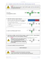
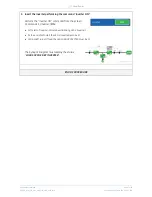
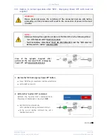
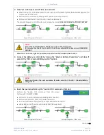
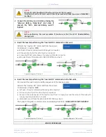
5. Insert the Inverter performing the “Inverter ON” command on all other units
.
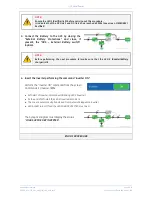
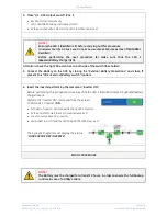
Do not start the next
Inverter
until the sequence of the previous ends.
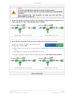
Perform the
“Inverter ON”
command from the screen:
Commands 1 / INVERTER /
ON
.
•
Soft-start
of
Inverter
indicated with blinking
LED 2 (Inverter)
.
•
At the end of Soft-start the
LED 2 (Inverter)
remains lit.
•
As soon as the output power of the
Inverters
is sufficient to supply the
Load
, the output of the units with
running
Inverter
will transfer to
Inverter
.
•
LED ALARM
turns Off and the
LED LOAD PROTECTED
must be lit.
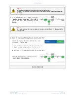
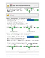
The
Synoptic Diagram
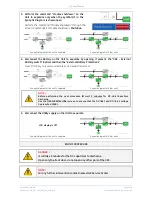
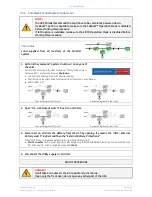
, on all UPS units, must display the status
“
LOAD SUPPLIED BY INVERTER”
.
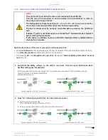
Synoptic Diagram of first unit
Synoptic Diagram of other units
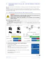
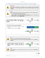
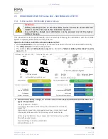
6. Operation mode selection.
TLE Series 160 - 500
is delivered normally selected for permanent
VFI
operation.
If available, the
eBoost™ Operation Mode
can be enabled and the
eBoost Start Time & eBoost Stop Time
can
be programmed for each day of the week (see
Section 6.4 SETUP / eBoost)
.
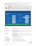
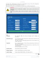
If available, the
IEMi Operation Mode
can be enabled and the
IEMi Start Time & IEMi Stop Time
can be
programmed for each day of the week (see
Section 6.4 SETUP / IEMi)
.
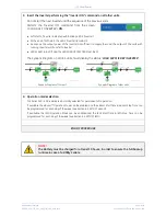
END OF PROCEDURE
NOTE !
The Battery must be charged for at least 10 hours, in order to ensure the full backup
runtime in case of a Utility Failure.

