CHAPTER 6: SETPOINTS
S3 PROTECTION
345 TRANSFORMER PROTECTION SYSTEM – INSTRUCTION MANUAL
6–87
the pickup level. However the pickup accuracy is guaranteed within the current input
accuracy of 3% above the set PKP value. The TOC pickup flag is asserted when the current
on any phase is above the PKP value. The TOC trip flag is asserted if the element stays
picked up for the time defined by the selected inverse curve and the magnitude of the
current. The element drops from pickup without operating if the measured current drops
below 97-99% of the pickup value before the time for operation is reached. When Definite
Time is selected, the time for TOC operation is defined only by the TDM setting. The
selection of Definite Time has a base time delay of 0.1 s, multiplied by the selected TD
multiplier. For example the operating time for TOC set to Definite Time and a TDM set to 5
will result in 5*0.1 = 0.5 s applying the time delay accuracy outlined under the Technical
Specification, and adding approximately 8 to 10 ms output relay time.
The following path is available using the keypad. For instructions on how to use the
keypad, please refer to
Chapter 3 - Working with the Keypad
.
PATH
:
SETPOINTS > S3 PROTECTION > SETPOINT GROUP 1(2) > PHASE TOC 1(2)
PH TOC1(2) FUNCTION
Range: Disabled, Latched Alarm, Alarm, Trip
Default: Disabled
The selection of the
Latched Alarm
,
Alarm
, or
Trip
setting enables the Phase TOC
function. The output relay #1 "Trip" will operate when the
Trip
setting is selected, and the
Phase TOC operates. The “ALARM” LED will not turn on if the TOC operates when set to
the function
Trip
. The “ALARM” LED will flash upon phase TOC operation, with the TOC
function selected as Alarm, and will self-reset, when the operating condition clears. Until
the reset command is initiated, if
Latched Alarm
is selected as a TOC function, the
“ALARM” LED will flash during TOC operation, and will stay “ON” after the operation
clears. The output relay #1 “Trip” will not operate if the
Latched Alarm
or
Alarm
setting
is selected.
PHASE CT INPUTS
Range: CT(W1), CT(W2)
Default: CT(W1)
The Phase Timed Overcurrent menu provides the selection of either CT(W1) input
currents or CT(W2) currents. If CT(W1) is selected, the PH TOC element will use the ratings
of the Winding 1 CTs entered on the relay under SYSTEM SETUP/S2 CURRENT SENSING. If
the CT(W2) setting is selected, the relay will use the CT ratings associated with
transformer Winding 2.
PH TOC1(2) PKP
Range: 0.04 to 20.00 x CT in steps of 0.01 x CT
Default: 1.00 x CT
This setting sets the time overcurrent pickup level, specified as times CT. For example, a
PKP setting of 0.9 x CT with 300:5 CT translates into 270A primary current.
PH TOC1(2) CURVE
Range: ANSI Extremely/Very/Moderately/Normally Inverse, Definite Time, IEC Curve A/B/C
and Short Inverse, IAC Extremely/Very/Inverse/Short
Default: Extremely Inverse
This setting sets the shape of the selected inverse curve.
PHASE TOC1(2) TDM
Range: 0.50 to 20.00 in steps of 0.01
Default: 1.00
This setting provides the selection for Time Dial Multiplier by which the times from the
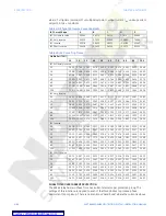
inverse curve are modified. For example if an ANSI Extremely Inverse curve is selected
with TDM = 2, and the fault current was 5 times bigger than the PKP level, the operation
of the element will not occur before an elapsed time after pickup, of 2.59 seconds.

