CHAPTER 6: SETPOINTS
S3 PROTECTION
345 TRANSFORMER PROTECTION SYSTEM – INSTRUCTION MANUAL
6–75
Restricted ground
fault
Depending on the SR345 order code, the relay provides up to two Restricted Ground Fault
elements per setpoint group; one per winding.
The Restricted Ground Fault (RGF) protection provides ground fault detection for low-
magnitude ground fault currents primarily for ground faults closed to the neutral point of
the wye connected winding. An internal ground fault on an impedance grounded wye
winding will produce a low magnitude ground fault current depending on position of the
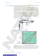
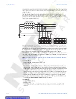
fault with respect of the winding neutral point. See the diagrams below, expressing the
dependence of the fault current with respect to the fault distance from the neutral point.
The resultant primary current can be negligible for ground winding faults within 30%
distance from the neutral point since the fault voltage is not the system voltage, but rather
the result of the transformation ratio between the primary windings and the percentage of
shorted turns. Therefore, the resultant differential currents may be below the pickup and/
or the slope setting of the main differential element, where the fault will go undetected.
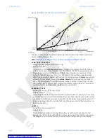
Application of the restricted ground fault protection extends the fault coverage towards
the neutral point.
Figure 22: RGF and percent differential zones of protection
Figure 23: Fault currents vs points from neutral
The SR345 implementation of the restricted ground fault protection is a low impedance
current differential scheme. The 345 calculates the magnitude of the ground differential
current as a difference between the vectors of the computed residual current, and the
measured ground current (i.e. 3I0- Ig), and applies a restraining current defined as the
Rg
35%
RGF
ZONE
DIFFERENTIAL
ZONE
WINDING
0
10
20
30
40
50
60
70
80
90
100
0
10
20
30
40
50
60
70
80
90
100
Ip(x)
Ifault(x)
%
Max
Ifault
Ifault
Ip
x = distance of fault from neutral


