CHAPTER 6: SETPOINTS
S3 PROTECTION
345 TRANSFORMER PROTECTION SYSTEM – INSTRUCTION MANUAL
6–67
Transformer percent
differential
The 345 provides one percent differential element per setpoint group. The settings menu of
the percent differential element defines a dual slope, dual breakpoint differential/restraint
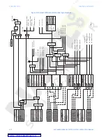
characteristic. The calculation of differential and restraint currents are as shown on the
figure below.
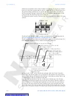
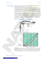
Figure 17: Calculation of transformer differential (Id) and restraint (Ir) currents
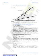
The 345 continuously calculates per-phase differential and restraint currents, and
compares their ratio with the user pre-defined differential/restraint characteristic. The
purpose of this characteristic is to provide a zone for differential protection operation, and
a zone for no operation, where the user can define protection sensitivity and dependability
during internal faults, and security during external faults.
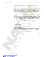
The differential current is calculated per-phase as a vector sum of currents from both
windings after magnitude and angle compensation.
Eq. 10
The restraint current is calculated as a maximum of the same internally compensated
currents:
Eq. 11
Winding 1
current
waveform
Winding 2
current
waveform
Phase angle and
zero sequence
compensation
(as required)
Magnitude, phase
angle and zero
sequence
compensation
(as required)
Decaying dc
offset filter
Decaying dc
offset filter
Discrete Fourrier
transform
Discrete Fourrier
transform
MAX
S
Differential
Current
Restraint
Current
897801.CDR


