


7–6
345 TRANSFORMER PROTECTION SYSTEM – INSTRUCTION MANUAL
M3 BREAKER MAINTENANCE
CHAPTER 7: MAINTENANCE
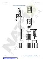
Figure 3: Trip circuits with continuous monitoring
The following path is available using the keypad. For instructions on how to use the
keypad, please refer to
Chapter 3 - Working with the Keypad
.
PATH
:
MAINTENANCE > M3 BKR MAINTENANCE > W1(W2) BKR TRIP
RLY1(2) COIL FUNCTION
Range: Disabled, Alarm, Latched Alarm
Default: Disabled
Selecting Alarm, or Latched Alarm, enables the RLY1(2) Coil Monitor monitoring function.
The “ALARM” and “MAINTENANCE” LEDs will light up upon detection of a RLY1(2) coil
circuitry problem. The “ALARM” LED will flash upon RLY1(2) Coil Monitor operating
condition, with the RLY1(2) Coil Monitor function selected as Alarm, and will self-reset,
when the condition clears. If Latched Alarm is selected, the “ALARM” LED will flash during
the RLY1(2) Coil Monitor condition, and will stay “ON” after the condition clears, until the
reset command is initiated. Any or all of output relays 3 to 6 can be selected to operate
when the RLY1(2) Coil Monitor function is selected as Alarm, or Latched Alarm.
Trip
Coil
DC -
R
By-pass
resistor
52a contact
External
jumper
V
A2
B3
A3
DC +
Output Relay 1 (TRIP)
897787.cdr
Trip
Coil
DC -
R
By-pass
resistor
52a contact
External
jumper
V
B4
A4
B5
DC +
Output Relay 2 (TRIP)
897788.cdr