CHAPTER 1: INTRODUCTION
DESCRIPTION OF THE 345 TRANSFORMER PROTECTION SYSTEM
345 TRANSFORMER PROTECTION SYSTEM – INSTRUCTION MANUAL
1–5
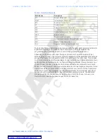
Table 1: Protection Elements
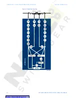
The 345 relay has two identical setpoint groups, with the same set of protection elements.
By default setpoint group 1 will be active. Setpoint group 2 can be activated by
programming the conditions under S4 Control/Change Setpoint Group menu.
Depending on the relay order code, the type and number of protection elements per
setpoint group changes. The full set of protection elements will be available in the setpoint
group, if the “Advanced configuration (letter M) is selected in the order code. This includes
one Transformer Percent Differential element, one Instantaneous Differential element, two
Restricted Ground Fault elements, one Thermal Model, two Breaker Failure elements, two
of each Phase-, Ground-, and Neutral Instantaneous Overcurrent elements, two of each
Phase-, Ground-, Neutral Timed Overcurrent elements, and two Negative Sequence Timed
Overcurrent elements. Some of the protection elements are common for the transformer
protection: Percent and Instantaneous differential elements, Thermal Model, and others
are generic with programmable AC inputs from either winding currents: the Restricted
Ground Fault 1(2), the Phase-, Ground-, and Neutral IOC1(2), the Phase-, Ground-, and
Neutral TOC1(2), and the Negative Sequence TOC1(2) elements.
ANSI Device
Description
87T
Percent Differential
50/87
Instantaneous Differential
87G
Restricted Ground Fault
49
Thermal Model
50P
Phase Instantaneous Overcurrent
50G
Ground/Sensitive Ground Instantaneous Overcurrent
50N
Neutral Instantaneous Overcurrent
50BF
Breaker Failure
51P
Phase Timed Overcurrent
51G
Ground/Sensitive Ground Timed Overcurrent
51N
Neutral Timed Overcurrent
51_2
Negative Sequence Timed Overcurrent


