background image

6–112

345 TRANSFORMER PROTECTION SYSTEM – INSTRUCTION MANUAL

S4 CONTROLS

CHAPTER 6: SETPOINTS

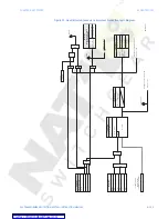
Figure 35: Virtual inputs scheme logic

Logic elements

The 345 relay has 16 Logic Elements available to build simple logic using the state of any 
programmed contact, virtual, or remote input, or from the output operand of a protection, 
or control element. Changing the state of any of the assigned inputs used as trigger 
sources, will change the state of the Logic Element, unless a blocking input is present. The 
logic provides for assigning up to three triggering inputs in an “OR” gate for Logic Element 
operation, and up to three blocking inputs in an “OR” gate for defining the block signal. 
Pickup and dropout timers are available for delaying Logic Element operation and drop-
out respectively. In addition, the user can define whether to use the “ON”, or “OFF” state of 
the programmed element by selecting ASSERTED: “On” or “Off”. 
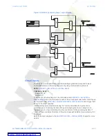
Referring to the Logic Element logic diagram below, the Logic Element can be set to one of 
four functions: 

Control

Alarm

Latched Alarm

, or 

Trip

. The Trip output relay will be 

triggered when 

Trip

 is selected as a function, and the Logic element operates. Output relay 

#1 (Trip) will not be triggered during Logic Element operation if 

Alarm

Latched Alarm

, or 

Control

 is selected.

The “PICKUP” LED will turn on upon a Logic Element pickup condition except when the 
Logic Element function is selected as 

Control

The “ALARM” LED will turn on upon Logic Element operation if the Logic Element function 
selected is either 

Alarm

, or 

Latched Alarm

The “TRIP” LED will turn on upon Logic Element operation if the Logic Element function is 
selected as 

Trip

The option to trigger auxiliary output relays is provided for any of the selected Logic 
Element functions.
The following path is available using the keypad.  For instructions on how to use the 
keypad, please refer to 

Chapter 3 - Working with the Keypad

.

PATH

SETPOINTS > S4 CONTROLS > S4 LOGIC ELEMENTS

LE1(16) FUNCTION

Range: Disabled, Control, Alarm, Latched Alarm, Trip
Default: Disabled

This setting defines the use of the Logic Element. When 

Trip

 is selected as a function, the 

Logic Element will trigger Output Relay # 1 (Trip) upon operation. 

SETPOINT

V INPUT FUNCTION

Disabled = 0

Enabled = 1

AND

SETPOINT

V INPUT 1 TYPE

Latched

Self-Reset

AND

AND

“Virtual Input 1 to ON = 1"

“Virtual Input 1 to OFF = 0"

S

R

LATCH

OR

ACTUAL VALUES

V INPUT 1 NAME:
(Operand)

V Input 1 Status

897774.cdr

From
Control
menu

Courtesy of NationalSwitchgear.com

Содержание SR345

Страница 1: ...nue Markham Ontario Canada L6E 1B3 Tel 905 294 6222 Fax 905 201 2098 Internet http www GEmultilin com Instruction manual 345 revision 1 41 Manual P N 1601 9098 A4 GE publication code GEK 113568C Copyright 2011 GE Multilin 1601 9098 A4 345 Transformer Protection System Transformer protection and control Courtesy of NationalSwitchgear com ...

Страница 2: ... SR3 Setup are registered trademarks of GE Multilin Inc The contents of this manual are the property of GE Multilin Inc This documentation is furnished on license and may not be reproduced in whole or in part without the permission of GE Multilin The content of this manual is for informational use only and is subject to change without notice Part number 1601 9098 A4 May 2011 Courtesy of NationalSw...

Страница 3: ...er polarity 2 9 Current inputs 2 10 Ground and sensitive ground CT inputs 2 10 Zero sequence CT installation 2 11 Control power 2 12 Contact inputs 2 12 Trip1 and Trip2 output relays 2 13 Serial communications 2 15 IRIG B 2 16 3 INTERFACES Front control panel interface 3 2 Description 3 3 Display 3 3 Working with the Keypad 3 3 LED status indicators 3 5 Relay messages 3 6 Target messages 3 6 Self ...

Страница 4: ...eatures 3 26 Transient recorder Waveform capture 3 26 Protection summary 3 29 Password security 3 30 4 ACTUAL VALUES Actual values 4 1 A1 Status 4 3 Clock 4 4 Contact inputs 4 4 Output relays 4 5 Logic elements 4 5 Virtual inputs 4 5 Remote inputs 4 5 Remote outputs 4 6 Contact inputs summary 4 6 Output relays summary 4 6 Logic elements summary 4 7 GOOSE status 4 7 GOOSE HDR status 4 7 A2 Metering...

Страница 5: ...l protection 6 80 Phase timed overcurrent protection 6 83 Phase instantaneous overcurrent protection 6 90 Ground timed overcurrent protection 6 93 Ground instantaneous overcurrent protection 6 97 Neutral timed overcurrent protection 6 100 Neutral instantaneous overcurrent protection 6 103 Negative sequence timed overcurrent protection 6 106 S4 Controls 6 109 Change setpoint group 6 109 Virtual inp...

Страница 6: ...345 TRANSFORMER PROTECTION SYSTEM INSTRUCTION MANUAL APPENDIX Change notes Appendix 1 Manual Revision history Appendix 1 Courtesy of NationalSwitchgear com ...

Страница 7: ...uipped with serial RS485 USB and Ethernet ports as well as a wide selection of protocols such as Modbus DNP3 0 IEC60870 5 103 60870 5 104 IEC 61850 GOOSE the 345 relay is the best in class for either MCCs SCADA or inter relay communications The 345 provides excellent accessibility and transparency with regard to power system conditions and events through both its four line 20 character display and...

Страница 8: ... icons are used to indicate notes cautions and dangers Figure 1 Note icons used in the documentation The standard note icon emphasizes a specific point or indicates minor problems that may occur if instructions are not properly followed The caution icon indicates that possible damage to equipment or data may occur if instructions are not properly followed The danger icon provides users with a warn...

Страница 9: ...nerVista SR3 Setup software for display and diagnostics Phasors Transients and Harmonics Current waveforms are processed twice every cycle with a DC Offset Filter and a Discrete Fourier Transform DFT The resulting phasors have fault current transients and all harmonics removed This results in an overcurrent relay that is extremely secure and reliable one that will not overreach Processing of AC Cu...

Страница 10: ...ODUCTION Figure 2 Single line diagram 897743 CDR 345 RELAY 50G 51G 50G 51G Metering Calculate Restraint Current Calculate Differential Currents Calculate Harmonics 2nd and 5th BLOCK 50P 50P 50G 50G 51P 51P 51G 51G 50BF 50BF 51_2 51_2 50N 50N 51N 51N 87G 87G 87T 50 87 Winding 2 Winding 1 49P Courtesy of NationalSwitchgear com ...

Страница 11: ...ailure elements two of each Phase Ground and Neutral Instantaneous Overcurrent elements two of each Phase Ground Neutral Timed Overcurrent elements and two Negative Sequence Timed Overcurrent elements Some of the protection elements are common for the transformer protection Percent and Instantaneous differential elements Thermal Model and others are generic with programmable AC inputs from either ...

Страница 12: ...ION SETPOINTS S1 RELAY SETUP S2 SYSTEM SETUP S3 PROTECTION S4 CONTROLS S5 INPUTS OUTPUTS MAINTENANCE M1 RELAY INFO M3 BKR MAINTENANCE M4 BKR MONITOR M5 RELAY MAINT M6 FACTORY SERVICE 897756A1 cdr XFMR PERCENT DIFF PCNT DIFF FUNCTION MINIMUM PICKUP SLOPE 1 BREAKPOINT 1 BREAKPOINT 2 SLOPE 2 PHASE TOC1 PHASE TOC1 FUNCTION PH TOC1 PICKUP PHASE CT INPUT PH TOC1 CURVE PH TOC1 TDM RLY1 TRIP W1 BKR RLY2 T...

Страница 13: ...RDER CODES 345 TRANSFORMER PROTECTION SYSTEM INSTRUCTION MANUAL 1 7 345 order codes The information to specify a 345 relay is provided in the following order code figure Figure 4 345 order codes Courtesy of NationalSwitchgear com ...

Страница 14: ...urve Shape ANSI Extremely Very Moderately Normally Inverse Definite Time IEC Curve A B C Short IAC Extremely Very Inverse Short Curve Multiplier 0 05 to 20 00 in steps of 0 01 Reset Time Instantaneous Linear Time Delay Accuracy 3 of expected inverse time or 1 cycle whichever is greater Level Accuracy per CT input SENSITIVE GROUND TIMED OVERCURRENT 51SG Ground Current Fundamental Pickup Level 0 005...

Страница 15: ...PKP TRANSFORMER PERCENT DIFFERENTIAL PROTECTION 87T Differential Restraint Characteristic Dual Slope Dual Breakpoint Minimum Pickup Level 0 05 to 1 00 x CT in steps of 0 01 Slope 1 Range 15 to 100 in steps of 1 Slope 2 Range 50 to 100 in steps of 1 Kneepoint 1 0 50 to 4 00 x CT in steps of 0 01 Kneepoint 2 1 00 to 10 00 x CT in steps of 0 01 2nd Harmonic Inhibit Level 1 0 to 40 0 insteps of 0 1 2n...

Страница 16: ... 1 CT 3 of reading from 0 02 to 3 CT 20 of reading from 0 002 to 0 019 CT CT withstand 1 second at 100 rated current 2 seconds at 40 rated current continuous at 3 rated current Data capture TRANSIENT RECORDER Buffer size 3 s No of buffers 1x192 3x64 6x32 No of channels 14 Sampling rate 32 samples per cycle Triggers Manual Command Contact Input Virtual Input Logic Element Element Pickup Trip Dropou...

Страница 17: ...ps of 0 01 x CT Dropout Level 97 to 98 of pickup Timer 1 Delay 0 03 to 1 00 s in steps of 0 01 s Timer 2 Delay 0 00 to 1 00 s in steps of 0 01 s Time Delay Accuracy 0 to 1 cycle Timer 1 Timer 2 Level Accuracy per CT input AMBIENT TEMPERATURE High Temperature Pickup 20 C to 80 C in steps of 1 C Low Temperature Pickup 40 C to 20 C in steps of 1 C Time Delay 1 to 60 min in steps of 1 min Temperature ...

Страница 18: ...t material silver alloy Operate time 8 ms Continuous current 10 A Make and carry for 0 2s 30 A per ANSI C37 90 Break DC inductive L R 40 ms 24 V 1 A 48 V 0 5 A 125 V 0 3 A 250 V 0 2 A Break DC resistive 24 V 10 A 48 V 6 A 125 V 0 5 A 250 V 0 3 A Break AC inductive 720 VA 250 VAC Pilot duty A300 Break AC resistive 277 VAC 10 A TRIP SEAL IN Relay 1 trip seal in 0 00 to 9 99 s in steps of 0 01 Relay ...

Страница 19: ... 0 Data transfer rate 115 kbps Testing and certification TESTING AND CERTIFICATION TEST REFERENCE STANDARD TEST LEVEL Dielectric voltage withstand 2 3KV Impulse voltage withstand EN60255 5 5KV Damped Oscillatory IEC61000 4 18IEC60255 22 1 2 5KV CM 1KV DM Electrostatic Discharge EN61000 4 2 IEC60255 22 2 Level 4 RF immunity EN61000 4 3 IEC60255 22 3 Level 3 Fast Transient Disturbance EN61000 4 4 IE...

Страница 20: ...mped Oscillatrory IEEE ANSI C37 90 1 2 5KV 1Mhz RF Immunity IEEE ANSIC37 90 2 20V m 80 1Ghz ESD IEEE ANSIC37 90 3 8KV CD 15KV AD UL508 e83849 NKCR Safety UL C22 2 14 e83849 NKCR7 UL1053 e83849 NKCR APPROVALS Applicable Council Directive According to Low voltage directive EN60255 5 EN60255 27 EN61010 1 CE compliance EMC Directive EN60255 26 EN50263 EN61000 6 2 UL508 North America cULus UL1053 C22 2...

Страница 21: ...echanical installation This section describes the mechanical installation of the 345 system including dimensions for mounting and information on module withdrawal and insertion Dimensions The dimensions of the 345 are shown below Additional dimensions for mounting and panel cutouts are shown in the following sections Courtesy of NationalSwitchgear com ...

Страница 22: ...TER 2 INSTALLATION Figure 1 345 dimensions Product identification The product identification label is located on the side panel of the 345 This label indicates the product model serial number firmware revision and date of manufacture Figure 2 345 label Courtesy of NationalSwitchgear com ...

Страница 23: ...d below CAUTION CAUTION To avoid the potential for personal injury due to fire hazards ensure the unit is mounted in a safe location and or within an appropriate enclosure Figure 3 Panel mounting Figure 4 Mounting tabs optional 1 From the front of the panel slide the empty case into the cutout until the bottom tab clicks into place see above BOTTOM TAB V TABS Courtesy of NationalSwitchgear com ...

Страница 24: ... outward to about 90 These tabs are located on the sides of the case and appear as shown above The relay can now be inserted and can be panel wired Figure 5 Panel cutout dimensions Unit withdrawal and insertion Figure 6 Unit withdrawal and insertion diagram 5 350 0 010 135 9 mm 0 25mm 4 100 0 010 104 1 mm 0 25 mm 0 200 5 1 mm Φ 6 900 0 010 175 3 mm 0 25 mm 6 000 0 010 152 4 mm 0 25 mm 4 000 0 010 ...

Страница 25: ... PANEL SURFACE THE HANDLE MUST BE ROTATED 90 WHILE SLIDING THE 345 DRAW OUT UNIT INTO THE CAPTIVE UNIT 8 32X3 8IN P HD PHIL BLK GE PART 1408 0306 QTY 8 TIGHTENING TORQUE 15 IN LB NOTE IT IS THE RESPONSIBILITY OF THE USER TO ENSURE THAT THE EQUIPMENT IS INSTALLED OPERATED AND USED FOR ITS INTENDED FUNCTION IN THE MANNER SPECIFIED BY THE MANUFACTURER IF THIS IS NOT THE CASE THEN THE SAFETY PROTECTIO...

Страница 26: ...IG B F1 F2 COMMUNICATIONS CONTROL POWER A B C E5 D5 E6 D6 E7 D7 E8 D8 IA IA IB IB IC IC IG IG 7 CRITICAL FAILURE RELAY 3 AUXILIARY 4 AUXILIARY 5 AUXILIARY 6 AUXILIARY 2 TRIP 1 TRIP OPTIONAL Front Panel Rear Panel 345 Transformer Protection System 52a 52b Winding 1 Breaker Aux Contacts E9 D9 E10 D10 E11 D11 E12 D12 IA IA IB IB IC IC IG IG WINDING 1 WINDING 2 52a 52b Winding 2 Breaker Aux Contacts 5...

Страница 27: ... 7 Terminal identification NOTE NOTE When installing two lugs on one terminal both lugs should be right side up as shown in the picture below This is to ensure the adjacent lower terminal block does not interfere with the lug body Figure 8 CORRECT INSTALLATION METHOD Courtesy of NationalSwitchgear com ...

Страница 28: ...2 8 345 TRANSFORMER PROTECTION SYSTEM INSTRUCTION MANUAL ELECTRICAL INSTALLATION CHAPTER 2 INSTALLATION Figure 9 INCORRECT INSTALLATION METHOD lower lug reversed Courtesy of NationalSwitchgear com ...

Страница 29: ...PUT 8 INPUT 9 INPUT 10 INPUT COM CHASSIS GND W1 PHASE A CT W1 PHASE B CT W1 PHASE C CT W1 GND CT W2 PHASE A CT W2 PHASE B CT W2 PHASE C CT W2 GND CT W1 PHASE A CT W1 PHASE B CT W1 PHASE C CT W1 GND CT W2 PHASE A CT W2 PHASE B CT W2 PHASE C CT W2 GND CT IRIG B IRIG B RS485 RS485 RS485 COM CHASSIS GND RESERVED RESERVED POWER SUPPLY CHASSIS GND W1 TRIP COM W2 TRIP N O W2 TRIP OPTV AUX 3 COM AUX 4 N C...

Страница 30: ...ee phase current phasors The following figures show three possible ground connections or three possible sensitive ground connections The ground inputs Terminals D8 and E8 for W1 and D12 and E12 for W2 are used in conjunction with a Zero Sequence CT as source or in the neutral of wye connected source CTs When using the residual connection set the GROUND CT PRIMARY setpoint to a value equal to the P...

Страница 31: ...re 12 Zero sequence core balance CT installation Transformer Winding 1 Transformer Winding 1 897730 CDR A B C GROUND CURRENT INPUT GROUND CURRENT INPUT SR345 PHASE CURRENT PHASE CURRENT INPUTS A B C GROUND CURRENT INPUT GROUND CURRENT INPUT WITH ZERO SEQUENCE CT WITH ZERO SEQUENCE CT GROUND CURRENT INPUT GROUND CURRENT INPUT WITH RESIDUAL CONNECTION WITH RESIDUAL CONNECTION E8 D8 G GROUND I N N IG...

Страница 32: ...copper braided shielding and bonding cable should be used As a minimum 96 strands of number 34 AWG should be used Belden catalog number 8660 is suitable CAUTION CAUTION Isolate power prior to servicing NOTE NOTE An external switch circuit breaker or other protective device must be connected near to the equipment Figure 13 Control power connection Contact inputs External contacts can be connected t...

Страница 33: ...ng feature resets but the breaker does not change state the output relay will be reset after a default interval of 2 seconds If neither of the breaker auxiliary contacts 52a nor 52b is programmed to a contact input the Trip Relay is de energized after either the delay programmed in the Breaker Failure feature or a default interval of 100 ms after the initiating input resets If a delay is programme...

Страница 34: ... trip circuit integrity NOTE NOTE To monitor the Trip coil circuit integrity use the relay terminals A2 and B3 to connect the Trip coil and provide a jumper between terminals A2 optional voltage and A3 NOTE NOTE To monitor the Trip coil circuit integrity use the relay terminals B4 and A4 to connect the Trip coil and provide a jumper between terminals B4 optional voltage and B5 Figure 15 Relay 1 Tr...

Страница 35: ... each RS485 port are tied together and grounded only once at the master or at the 345 Failure to do so may result in intermittent or failed communications The source computer PLC SCADA system should have similar transient protection devices installed either internally or externally Ground the shield at one point only as shown in the figure above to avoid ground loops Correct polarity is also essen...

Страница 36: ...ed AM form The type of form is auto detected by the 345 relay Third party equipment is available for generating the IRIG B signal this equipment may use a GPS satellite system to obtain the time reference so that devices at different geographic locations can also be synchronized Figure 18 IRIG B connection GE MULTILIN 345 RELAY IRIG B RECEIVER TO OTHER DEVICES RG58 59 COAXIAL CABLE GPS SATELLITE S...

Страница 37: ...rotection System Interfacing via the relay keypad and display Interfacing via the EnerVista SR3 Setup software This section provides an overview of the interfacing methods available with the 345 using the relay control panels and EnerVista SR3 Setup software For additional details on interface parameters for example settings actual values etc refer to the individual chapters Courtesy of NationalSw...

Страница 38: ...igure 1 Transformer Protection System Front Panel ENTER MENU ESCAPE RESET 897351A1 cdr USB GE Multilin SR345 Transformer Protection System IN SERVICE TROUBLE SETPOINT GROUP 1 SETPOINT GROUP 2 TRIP ALARM PICKUP MAINTENANCE W1 BREAKER OPEN W1 BREAKER CLOSED W1 BREAKER OPEN W2 BREAKER OPEN W2 BREAKER CLOSED Courtesy of NationalSwitchgear com ...

Страница 39: ...ormation is displayed after a user defined period of inactivity Pressing the Menu key during the display of default message returns the display to the last message shown before the default message appeared Any trip alarm or pickup is displayed immediately automatically overriding the default message Working with the Keypad The 345 display messages are organized into a Main Menu pages and sub pages...

Страница 40: ...o store altered setpoint values into memory to complete the change The MESSAGE key can also be used to enter sub pages but not to store altered setpoints The ESCAPE key is also dual purpose It is used to exit the sub pages and to cancel a setpoint change The MESSAGE key can also be used to exit sub pages and to cancel setpoint changes The VALUE keys are used to scroll through the possible choices ...

Страница 41: ...ondition has cleared ALARM Amber This LED will flash upon detection of an alarm condition with element functions selected as alarm The LED will automatically turn off if the alarm condition clears The LED will remain steady ON if the function of the operated protection was selected as latched alarm PICKUP Amber This indicator will light ON upon pickup condition generated by any of the relay featur...

Страница 42: ...et Messages can be reviewed by pressing either the MESSAGE UP or MESSAGE DOWN key If a RESET command is not performed but any of the other faceplate pushbuttons is pressed the display will not show the target messages unless the user navigates to ACTUAL VALUES A4 TARGET MESSAGES where they can be reviewed If the target messages have not been cleared before the user presses a pushbutton different f...

Страница 43: ...y the cause of major self test failure Record the major self test failure in the Event Recorder Figure 6 Typical Self test warning Table 1 Minor Self test Errors Self test Error Message Latched Target Message Description of Problem How Often the Test is Performed What to do MAINTENANCE ALERT IRIG B Failure No A bad IRIG B input signal has been detected Every 5 seconds Ensure IRIG B cable is connec...

Страница 44: ...sage appears upon an attempt to enter an incorrect password as part of password security Self test Error Message Latched Target Message Description of Problem How Often the Test is Performed What to do UNIT FAILURE Contact Factory XXXX Yes This warning is caused by a unit hardware failure Failure code XXXX is shown Every 5 seconds1 1 Failure is logged after the detection of 5 consecutive failures ...

Страница 45: ...s accessed from the Tree which launches on clicking EnerVista SR3 Setup Software Although settings can be entered manually using the control panel keys a PC can be used to download setpoints through the communications port The EnerVista SR3 Setup software is available from GE Multilin to make this as convenient as possible With EnerVista SR3 Setup running it is possible to Program and modify setti...

Страница 46: ...ed and running properly At least 100 MB of hard disk space is available At least 256 MB of RAM is installed The EnerVista SR3 Setup software can be installed from either the GE EnerVista CD or the GE Multilin website at http www GEmultilin com Installing the EnerVista SR3 Setup software After ensuring the minimum requirements indicated earlier use the following procedure to install the EnerVista S...

Страница 47: ...the complete path including the new directory name where the EnerVista SR3 Setup software will be installed 8 Click on Next to begin the installation The files will be installed in the directory indicated the USB driver will be loaded into the computer and the installation program will automatically create icons and add EnerVista SR3 Setup software to the Windows start menu 9 The 345 device will b...

Страница 48: ...m your computer to the 345 Relay using the USB port 10 Plug the USB cable into the USB port on the 345 Relay then into the USB port on your computer 11 Launch EnerVista SR3 Setup from LaunchPad 12 In EnerVista Device Setup 13 Select USB as the Interface type 14 Select 345 Relay as the USB device Courtesy of NationalSwitchgear com ...

Страница 49: ... 2 Click on the Device Setup button to open the Device Setup window and click the Add Site button to define a new site 3 Enter the desired site name in the Site Name field If desired a short description of the site can also be entered In this example we will use New Site 1 as the site name 4 The new site will appear in the upper left list in the EnerVista SR3 Setup window 5 Click the Add Device bu...

Страница 50: ...ing window will appear when the QuickConnect button is pressed As indicated by the window the Quick Connect feature can quickly connect the EnerVista SR3 Setup software to a 345 front port if the USB is selected in the interface drop down list Select 345 Relay and press the Connect button Ethernet can also be used as the interface for Quick Connect as shown above When connected a new Site called Q...

Страница 51: ...le from the GE EnerVista CD See the previous section for the installation procedure 2 Click on the Device Setup button to open the Device Setup window and click the Add Site button to define a new site 3 Enter the desired site name in the Site Name field If desired a short description of the site can also be entered In this example we will use Substation 1 as the site name 4 The new site will appe...

Страница 52: ...ner of the main EnerVista SR3 Setup window The 345 Site Device has now been configured for Ethernet communications Proceed to the following section to begin communications Connecting to the relay Now that the communications parameters have been properly configured the user can easily communicate with the relay 1 Expand the Site list by double clicking on the site name or clicking on the box to lis...

Страница 53: ...ged and resized at will Working with setpoints and setpoint files Engaging a device The EnerVista SR3 Setup software may be used in on line mode relay connected to directly communicate with a relay Communicating relays are organized and grouped by communication interfaces and into sites Sites may contain any number of relays selected from the product series Entering setpoints The System Setup page...

Страница 54: ...the values into the 345 Click YES to accept any changes and exit the window Click Restore to retain previous values Click Default to restore Default values File support Opening any EnerVista SR3 Setup file will automatically launch the application or provide focus to the already opened application If the file is a settings file has a SR3 extension which had been removed from the Settings List tree...

Страница 55: ...eating new setpoint files The setpoint files in the EnerVista SR3 Setup window are accessed in the Files Window Use the following procedure to download and save setpoint files to a local PC 1 Ensure that the site and corresponding device s have been properly defined and configured as shown in Connecting EnerVista SR3 Setup to the Relay above 2 Select the desired device from the site list 3 Select ...

Страница 56: ...owse for the file to be added then click Open The new file and complete path will be added to the file list Creating a new setpoint file The EnerVista SR3 Setup software allows the user to create new setpoint files independent of a connected device These can be uploaded to a relay at a later date The following procedure illustrates how to create new setpoint files 1 In the File pane right click on...

Страница 57: ... to the EnerVista SR3 Setup software environment Upgrading setpoint files to a new revision It is often necessary to upgrade the revision for a previously saved setpoint file after the 345 firmware has been upgraded This is illustrated in the following procedure 1 Establish communications with the 345 relay 2 Select the Maintenance M1 Relay Info menu item and record the Firmware Revision 3 Load th...

Страница 58: ...ns on loading this setpoint file into the 345 Printing setpoints and actual values The EnerVista SR3 Setup software allows the user to print partial or complete lists of setpoints and actual values Use the following procedure to print a list of setpoints 1 Select a previously saved setpoints file in the File pane or establish communications with a 345 device 2 From the main window select the Offli...

Страница 59: ...so be printed from a connected device with the following procedure 1 Establish communications with the desired 345 device 2 From the main window select the Online Print Device Information menu item 3 The Print Export Options dialog box will appear Select Actual Values in the upper section and select either Include All Features for a complete list or Include Only Enabled Features for a list of only...

Страница 60: ... Device item 4 Select the target relay from the list of devices shown and click Send If there is an incompatibility an Incompatible Device error will occur If there are no incompatibilities between the target device and the settings file the data will be transferred to the relay An indication of the percentage completed will be shown in the bottom of the main window Upgrading relay firmware To upg...

Страница 61: ...h of the new firmware file has been transferred and the upgrade status The entire transfer process takes approximately 10 minutes 6 The EnerVista SR3 Setup software will notify the user when the 345 has finished loading the file Carefully read any displayed messages and click OK to return the main screen Cycling power to the relay is recommended after a firmware upgrade After successfully updating...

Страница 62: ...ondition With EnerVista SR3 Setup software running and communications established select the Actual Values A3 Records Transient Records menu item to open the Transient Recorder Viewer window Click on Trigger Waveform to trigger a waveform capture Waveform file numbering starts with the number zero in the 345 so that the maximum trigger number will always be one less than the total number of trigge...

Страница 63: ...Preference button to open the COMTRADE Setup page in order to change the graph attributes Display graph values at the corresponding cursor line Cursor lines are identified by their colors FILE NAME Indicates the file name and complete path if saved CURSOR LINES To move lines locate the mouse pointer over the cursor line then click and drag the cursor to the new position TRIGGER LINE Indicates the ...

Страница 64: ...tions as required by checking the appropriate boxes Click OK to store these graph attributes and to close the window The Waveform Capture window will reappear based on the selected graph attributes To view a vector graph of the quantities contained in the waveform capture press the Vector Display button to display the following window Preference Button Courtesy of NationalSwitchgear com ...

Страница 65: ... from Grouped Elements Control Elements and Maintenance screens Protection Summary Screen allows the User to view the output relay assignments for the elements modify the output relay assignments for the elements view the enable disable status of Control Elements navigate to the respected Protection Element screen on a button click The Protection Summary screen is as follows Courtesy of NationalSw...

Страница 66: ... well as a central administrative authority then the use of the password system is highly encouraged The feature robustness of this system requires it to be managed exclusively through the EnerVista setup software This section describes how to perform the initial setup For more details on the password security feature refer to Password Security in Chapter 6 1 345 devices shipped from the factory a...

Страница 67: ... level The Master Level permits setup of the Remote and Local Passwords If the Master Reset Password has been lost record the Encrypted Key and contact the factory to have it decrypted 3 With Master Level access the user may disable password security altogether or change the Master Reset Password 4 The Master Access level allows programming of the Remote Setpoint and Remote Control passwords These...

Страница 68: ...the initial NULL value to a valid one Local Passwords must be 3 to 10 characters in length 6 If any Remote password has never been set that level will not be attainable except when logged in as the Master Level The same logic applies to the Local passwords 7 When passwords have been set the user will be prompted to enter the appropriate password depending on the interface being used remote or loca...

Страница 69: ...values Digital Energy Multilin Actualvalues Actual values All measured values the status of digital inputs and outputs and fault analysis information are accessed in Actual Values mode Actual value messages are organized into logical groups for easy reference as shown below Courtesy of NationalSwitchgear com ...

Страница 70: ...RL CURRENT W1 SNS GND CURRENT W1 NEG SEQ CURRENT W1 GND DIFF CURRENT A3 EVENT RECORDS E30 Date Record Time E29 Date Record Time A3 CLEAR TRANST REC TRANSIENT RECORDS CLEAR A4 TARGET MESSAGES PH IOC1 TRIP PH TOC TRIP A3 TRANSIENT RECORDS FORCE TRIGGER TOTAL RECORDS AVAILABLE RECORDS LAST CLEARED A2 WINDING 2 CURRENTS W2 PH A CURRENT W2 PH B CURRENT W2 PH C CURRENT W2 NTRL CURRENT W2 SNS GND CURRENT...

Страница 71: ...cdr A1 LOGIC ELEMENTS LOGIC ELEMENT 1 2 16 LOGIC ELEMENT LOGIC ELEMENT A1 VIRTUAL INPUTS 1 2 32 VIRTUAL INPUT VIRTUAL INPUT VIRTUAL INPUT A1 REMOTE INPUTS 1 2 32 REMOTE INPUT REMOTE INPUT REMOTE INPUT A1 OUTPUTS 1 2 32 REMOTE REMOTE OUTPUT REMOTE OUTPUT REMOTE OUTPUT A1 OUTPUT RELAYS R1 TRIP OUTPUT RELAY 7 R2 TRIP OUTPUT RELAY 3 A1 GOOSE HDR STATUS GOOSE 1 H STATUS GOOSE 8 H STATUS GOOSE 2 H STATU...

Страница 72: ...52b W1 BRK CI 2 Contact Input 2 OFF Range Off On The status of this contact shows the W1 breaker close open state when wired to a 52b breaker auxiliary contact 52a W2 BRK CI 3 Contact Input 3 OFF Range Off On The status of this contact shows the W2 breaker close open state when wired to a 52a breaker auxiliary contact 52b W2 BRK CI 4 Contact Input 4 OFF Range Off On The status of this contact show...

Страница 73: ... OUTPUT RELAY 7 Critical Failure Relay Range Off On The ON state indicates that the relay is in service Logic elements PATH ACTUAL VALUES A1 STATUS LOGIC ELEMENTS LOGIC ELEMENT 1 to 16 OFF Range Off On The state ON or OFF for each logic element depends on its programmed logic triggering inputs blocking inputs plus any pickup and or reset time delay Virtual inputs The state of all active virtual in...

Страница 74: ...TH ACTUAL VALUES A1 STATUS OUT RELAYS SUMMARY OUTPUT RELAYS SUMMARY This display shows a summary of the states of all output relays NOTE NOTE Output relay 7 is the Critical Failure relay used to indicate the correct functioning of the 345 relay This output relay shows the status ON when the 345 relay is powered up and set to Ready and no self test alarms are active under SETPOINTS S1 RELAY SETUP S...

Страница 75: ...tes of all logic elements GOOSE status PATH ACTUAL VALUES A1 STATUS GOOSE STATUS GOOSE 1 TO 8 Status Range OFF ON Default OFF GOOSE HDR status PATH ACTUAL VALUES A1 STATUS GOOSE HDR STATUS GOOSE 1 TO 8 H Status Range OFF ON Default OFF LE 1 OFF LE 9 OFF LE 2 OFF LE 10 OFF LE 3 OFF LE 11 OFF LE 4 OFF LE 12 OFF LE 5 OFF LE 13 OFF LE 6 OFF LE 14 OFF LE 7 OFF LE 15 OFF LE 8 OFF LE 16 OFF Courtesy of N...

Страница 76: ...dability All phasors and symmetrical components are referenced to the phase A current phasor By scrolling the Up Down keys the relay shows one by one all metered values as follows WINDING 1 CURRENT W1 PH A CURRENT 0 0 A 0o lag Range 1 to 6000 A 0 to 359o lag W1 PH B CURRENT 0 0 A 0o lag Range 1 to 6000 A 0 to 359o lag W1 PH C CURRENT 0 0 A 0o lag Range 1 to 6000 A 0 to 359o lag W1 NTRL CURRENT 0 0...

Страница 77: ... 1 to 6000 A 0 to 359o lag W2 PH C CURRENT 0 0 A 0o lag Range 1 to 6000 A 0 to 359o lag W2 NTRL CURRENT 0 0 A 0o lag Range 1 to 6000 A 0 to 359o lag W2 GND CURRENT 0 0 A 0o lag Range 1 to 6000 A 0 to 359o lag W2 SENS GND CURRENT 0 0 A 0o lag Range 1 to 600 A 0 to 359o lag W2 NEG SEQ CURRENT 0 0 A 0o lag Range 1 to 6000 A 0 to 359o lag W2 GND DIFF CURRENT 0 00 x CT 0o lag Courtesy of NationalSwitch...

Страница 78: ... CT 0o lag PH A RESTR CURRENT 0 00 x CT 0o lag DIFF 2 HARM PH A 0 0 f0 DIFF 5 HARM PH A 0 0 f0 PH B DIFF CURRENT 0 00 x CT 0o lag PH B RESTR CURRENT 0 00 x CT 0o lag DIFF 2 HARM PH B 0 0 f0 DIFF 5 HARM PH B 0 0 f0 PH C DIFF CURRENT 0 00 x CT 0o lag PH C RESTR CURRENT 0 00 x CT 0o lag DIFF 2 HARM PH C 0 0 f0 DIFF 5 HARM PH C 0 0 f0 Courtesy of NationalSwitchgear com ...

Страница 79: ...NG 345 TRANSFORMER PROTECTION SYSTEM INSTRUCTION MANUAL 4 11 TRANSFORMER THERMAL CAPACITY CURRENTS THERM CAP PH A 0 0 Range 1 to 150 THERM CAP PH B 0 0 Range 1 to 150 THERM CAP PH C 0 0 Range 1 to 150 Courtesy of NationalSwitchgear com ...

Страница 80: ...in the case where control power is lost Shown below is an example of an event record caused by a Breaker Open operation and the recorded information at the time of this record PATH ACTUAL VALUES A3 RECORDS EVENT RECORDS Table 1 Example of Event Record A3 EVENT REC T 5655 E5655 Jan 05 10 Ph IOC1 Trip OP 17 32 28 376 E5655 TRIP Ph IOC1 Trip OP W1 Ia x CT W1 0 08 x CT 0 Lag E5655 TRIP Ph IOC1 Trip OP...

Страница 81: ...5 TRIP Ph IOC1 Trip OP W2 Igr x CT W2 0 00 x CT E5655 TRIP Ph IOC1 Trip OP W2 I_2 x CT W1 0 00 x CT E5655 TRIP Ph IOC1 Trip OP Ph A Diff x CT W1 0 08 E5655 TRIP Ph IOC1 Trip OP Ph BDiff x CT W1 0 00 E5655 TRIP Ph IOC1 Trip OP Ph C Diff x CT W1 0 00 E5655 TRIP Ph IOC1 Trip OP Ph A Rest x CT W1 0 00 E5655 TRIP Ph IOC1 Trip OP Ph B Rest x CT W1 0 00 E5655 TRIP Ph IOC1 Trip OP Ph C Rest x CT W1 0 00 E...

Страница 82: ...opout Events DROPOUT These are events that occur when a protection element drops out after a corresponding pickup event Contact Input Events C INPUT These are events that occur when a contact input changes its state Virtual Input Events V INPUT These are events that occur when a virtual input changes its state Remote Input Events R INPUT These are events that occur when a remote input changes its ...

Страница 83: ...ct IN 4 On 0x0044 Contact IN 5 On 0x0045 Contact IN 6 On 0x0046 Contact IN 7 On 0x0047 Contact IN 8 On 0x0048 Contact IN 9 On 0x0049 Contact IN 10 On 0x0060 Contact IN 1 Off 0x0061 Contact IN 2 Off 0x0062 Contact IN 3 Off 0x0063 Contact IN 4 Off 0x0064 Contact IN 5 Off 0x0065 Contact IN 6 Off 0x0066 Contact IN 7 Off 0x0067 Contact IN 8 Off 0x0068 Contact IN 9 Off 0x0069 Contact IN 10 Off 0x0080 Vi...

Страница 84: ... On 0x009D Virtual IN 30 On 0x009E Virtual IN 31 On 0x009F Virtual IN 32 On 0x00A0 Virtual IN 1 Off 0x00A1 Virtual IN 2 Off 0x00A2 Virtual IN 3 Off 0x00A3 Virtual IN 4 Off 0x00A4 Virtual IN 5 Off 0x00A5 Virtual IN 6 Off 0x00A6 Virtual IN 7 Off 0x00A7 Virtual IN 8 Off 0x00A8 Virtual IN 9 Off 0x00A9 Virtual IN 10 Off 0x00AA Virtual IN 11 Off 0x00AB Virtual IN 12 Off 0x00AC Virtual IN 13 Off 0x00AD V...

Страница 85: ...CB Remote IN 12 On 0x01CC Remote IN 13 On 0x01CD Remote IN 14 On 0x01CE Remote IN 15 On 0x01CF Remote IN 16 On 0x01D0 Remote IN 17 On 0x01D1 Remote IN 18 On 0x01D2 Remote IN 19 On 0x01D3 Remote IN 20 On 0x01D4 Remote IN 21 On 0x01D5 Remote IN 22 On 0x01D6 Remote IN 23 On 0x01D7 Remote IN 24 On 0x01D8 Remote IN 25 On 0x01D9 Remote IN 26 On 0x01DA Remote IN 27 On 0x01DB Remote IN 28 On 0x01DC Remote...

Страница 86: ...FA Remote IN 27 Off 0x01FB Remote IN 28 Off 0x01FC Remote IN 29 Off 0x01FD Remote IN 30 Off 0x01FE Remote IN 31 Off 0x01FF Remote IN 32 Off 0x8041 Therm O L Trip PKP 0x8042 Therm O L Trip OP 0x8044 Therm O L Trip DPO 0x8049 Therm PhA Trip PKP 0x804A Therm PhA Trip OP 0x804C Therm PhA Trip DPO 0x8051 Therm PhB Trip PKP 0x8052 Therm PhB Trip OP 0x8054 Therm PhB Trip DPO 0x8061 Therm PhC Trip PKP 0x8...

Страница 87: ...11 Ph B IOC1 Trip PKP 0x9012 Ph B IOC1 Trip OP 0x9014 Ph B IOC1 Trip DPO 0x9021 Ph C IOC1 Trip PKP 0x9022 Ph C IOC1 Trip OP 0x9024 Ph C IOC1 Trip DPO 0x9041 Ntrl IOC1 Trip PKP 0x9042 Ntrl IOC1 Trip OP 0x9044 Ntrl IOC1 Trip DPO 0x9081 Gnd IOC1 Trip PKP 0x9082 Gnd IOC1 Trip OP 0x9084 Gnd IOC1 Trip DPO 0x90C1 Ph TOC1 Trip PKP 0x90C2 Ph TOC1 Trip OP 0x90C4 Ph TOC1 Trip DPO 0x90C9 Ph A TOC1 Trip PKP 0x...

Страница 88: ... PKP 0x9202 Gnd IOC2 Trip OP 0x9204 Gnd IOC2 Trip DPO 0x9241 Ph TOC2 Trip PKP 0x9242 Ph TOC2 Trip OP 0x9244 Ph TOC2 Trip DPO 0x9249 Ph A TOC2 Trip PKP 0x924A Ph A TOC2 Trip OP 0x924C Ph A TOC2 Trip DPO 0x9251 Ph B TOC2 Trip PKP 0x9252 Ph B TOC2 Trip OP 0x9254 Ph B TOC2 Trip DPO 0x9261 Ph C TOC2 Trip PKP 0x9262 Ph C TOC2 Trip OP 0x9264 Ph C TOC2 Trip DPO 0x9281 Ntrl TOC2 Trip PKP 0x9282 Ntrl TOC2 T...

Страница 89: ...P 0x9784 RGF2 Trip DPO 0x97C1 Inst Diff Trip PKP 0x97C2 Inst Diff Trip OP 0x97C4 Inst Diff Trip DPO 0x9801 NSeq TOC1 Trip PKP 0x9802 NSeq TOC1 Trip OP 0x9804 NSeq TOC1 Trip DPO 0x9841 NSeq TOC2 Trip PKP 0x9842 NSeq TOC2 Trip OP 0x9844 NSeq TOC2 Trip DPO 0x99C1 SGnd TOC2 Trip PKP 0x99C2 SGnd TOC2 Trip OP 0x99C4 SGnd TOC2 Trip DPO 0x9C01 LE 9 Trip PKP 0x9C02 LE 9 Trip OP 0x9C04 LE 9 Trip DPO 0x9C41 ...

Страница 90: ... Relay Not Ready 0xA4C1 LE 1 Alarm PKP 0xA4C2 LE 1 Alarm OP 0xA4C4 LE 1 Alarm DPO 0xA501 LE 2 Alarm PKP 0xA502 LE 2 Alarm OP 0xA504 LE 2 Alarm DPO 0xA541 LE 3 Alarm PKP 0xA542 LE 3 Alarm OP 0xA544 LE 3 Alarm DPO 0xA581 LE 4 Alarm PKP 0xA582 LE 4 Alarm OP 0xA584 LE 4 Alarm DPO 0xA5C1 LE 5 Alarm PKP 0xA5C2 LE 5 Alarm OP 0xA5C4 LE 5 Alarm DPO 0xA601 LE 6 Alarm PKP 0xA602 LE 6 Alarm OP 0xA604 LE 6 Ala...

Страница 91: ...O 0xB011 Ph B IOC1 Alrm PKP 0xB012 Ph B IOC1 Alrm OP 0xB014 Ph B IOC1 Alrm DPO 0xB021 Ph C IOC1 Alrm PKP 0xB022 Ph C IOC1 Alrm OP 0xB024 Ph C IOC1 Alrm DPO 0xB041 Ntrl IOC1 Alrm PKP 0xB042 Ntrl IOC1 Alrm OP 0xB044 Ntrl IOC1 Alrm DPO 0xB081 Gnd IOC1 Alarm PKP 0xB082 Gnd IOC1 Alarm OP 0xB084 Gnd IOC1 Alarm DPO 0xB0C1 Ph TOC1 Alarm PKP 0xB0C2 Ph TOC1 Alarm OP 0xB0C4 Ph TOC1 Alarm DPO 0xB0C9 Ph A TOC1...

Страница 92: ... OP 0xB204 Gnd IOC2 Alarm DPO 0xB241 Ph TOC2 Alarm PKP 0xB242 Ph TOC2 Alarm OP 0xB244 Ph TOC2 Alarm DPO 0xB249 Ph A TOC2 Alrm PKP 0xB24A Ph A TOC2 Alrm OP 0xB24C Ph A TOC2 Alrm DPO 0xB251 Ph B TOC2 Alrm PKP 0xB252 Ph B TOC2 Alrm OP 0xB254 Ph B TOC2 Alrm DPO 0xB261 Ph C TOC2 Alrm PKP 0xB262 Ph C TOC2 Alrm OP 0xB264 Ph C TOC2 Alrm DPO 0xB281 Ntrl TOC2 Alrm PKP 0xB282 Ntrl TOC2 Alrm OP 0xB284 Ntrl TO...

Страница 93: ... Inst Diff Alrm PKP 0xB7C2 Inst Diff Alrm OP 0xB7C4 Inst Diff Alrm DPO 0xB801 NSeq TOC1 Alrm PKP 0xB802 NSeq TOC1 Alrm OP 0xB804 NSeq TOC1 Alrm DPO 0xB841 NSeq TOC2 Alrm PKP 0xB842 NSeq TOC2 Alrm OP 0xB844 NSeq TOC2 Alrm DPO 0xB9C1 SGnd TOC2 Alrm PKP 0xB9C2 SGnd TOC2 Alrm OP 0xB9C4 SGnd TOC2 Alrm DPO 0xBC01 LE 9 Alarm PKP 0xBC02 LE 9 Alarm OP 0xBC04 LE 9 Alarm DPO 0xBC41 LE 10 Alarm PKP 0xBC42 LE ...

Страница 94: ...C1C2 Output Relay 2 On 0xC1C4 Output Relay 2 Off 0xC202 BKR Connected 0xC2C2 BKR2 Connected 0xC4C1 LE 1 PKP 0xC4C2 LE 1 OP 0xC4C4 LE 1 DPO 0xC501 LE 2 PKP 0xC502 LE 2 OP 0xC504 LE 2 DPO 0xC541 LE 3 PKP 0xC542 LE 3 OP 0xC544 LE 3 DPO 0xC581 LE 4 PKP 0xC582 LE 4 OP 0xC584 LE 4 DPO 0xC5C1 LE 5 PKP 0xC5C2 LE 5 OP 0xC5C4 LE 5 DPO 0xC601 LE 6 PKP 0xC602 LE 6 OP 0xC604 LE 6 DPO 0xC641 LE 7 PKP 0xC642 LE ...

Страница 95: ... Ntrl TOC1 OP 0xD104 Ntrl TOC1 DPO 0xD141 Gnd TOC1 PKP 0xD142 Gnd TOC1 OP 0xD144 Gnd TOC1 DPO 0xD181 Ph IOC2 PKP 0xD182 Ph IOC2 OP 0xD184 Ph IOC2 DPO 0xD1C1 Ntrl IOC2 PKP 0xD1C2 Ntrl IOC2 OP 0xD1C4 Ntrl IOC2 DPO 0xD201 Gnd IOC2 PKP 0xD202 Gnd IOC2 OP 0xD204 Gnd IOC2 DPO 0xD241 Ph TOC2 PKP 0xD242 Ph TOC2 OP 0xD244 Ph TOC2 DPO 0xD281 Ntrl TOC2 PKP 0xD282 Ntrl TOC2 OP 0xD284 Ntrl TOC2 DPO 0xD2C1 Gnd ...

Страница 96: ... 0xD9C1 SGnd TOC2 PKP 0xD9C2 SGnd TOC2 OP 0xD9C4 SGnd TOC2 DPO 0xDA02 BKR2 52a Cont OP 0xDA04 BKR2 52a Cont DPO 0xDA42 BKR2 52b Cont OP 0xDA44 BKR2 52b Cont DPO 0xDA82 BKR2 Stat Open OP 0xDA84 BKR2 Stat Open DPO 0xDAC1 BKR2 Stat Clsd PKP 0xDAC2 BKR2 Stat Clsd OP 0xDAC4 BKR2 Stat Clsd DPO 0xDB01 Trip BKR 1 PKP 0xDB02 Trip BKR 1 OP 0xDB04 Trip BKR 1 DPO 0xDB41 Trip BKR 2 PKP 0xDB42 Trip BKR 2 OP 0xD...

Страница 97: ...lck OP 0xE044 Therm O L Blck Off 0xE182 Output Relay 1 BLK 0xE184 Relay 1 BLK Off 0xE1C2 Output Relay 2 BLK 0xE1C4 Relay 2 BLK Off 0xE882 Group Change Blk 0xE884 Grp Change Blk DPO 0xF002 Ph IOC1 Block 0xF004 Ph IOC1 Block DPO 0xF042 Ntrl IOC1 Block 0xF044 Ntrl IOC1 Blk DPO 0xF082 Gnd IOC1 Block 0xF084 Gnd IOC1 Block DPO 0xF0C2 Ph TOC1 Block 0xF0C4 Ph TOC1 Block DPO 0xF102 Ntrl TOC1 Block 0xF104 N...

Страница 98: ... DPO 0xF702 Pcnt Diff Block 0xF704 Ph Diff Block DPO 0xF742 RGF1 Block 0xF744 RGF1 Block DPO 0xF782 RGF2 Block 0xF784 RGF2 Block DPO 0xF7C2 Inst Diff Block 0xF7C4 Inst Diff BlockDPO 0xF802 NSeq TOC1 Blk 0xF804 NSeq TOC1 Blk DPO 0xF842 NSeq TOC2 Blk 0xF844 NSeq TOC2 Blk DPO 0xF9C2 SGnd TOC2 Block 0xF9C4 SGnd TOC2 Blk DPO 0xFB02 Trip BKR1 Blk 0xFB04 Trip BKR1 Blk DPO 0xFB42 Trip BKR2 Blk 0xFB44 Trip...

Страница 99: ...ACTUAL VALUES A3 RECORDS CLEAR EVENT REC CLEAR No Range No Yes When set to Yes pressing the ENTER key will clear all event records Clear transient record PATH ACTUAL VALUES A3 RECORDS CLEAR TRANST REC CLEAR No Range No Yes When set to Yes pressing the ENTER key will clear all transient records Clear thermal capacity record PATH ACTUAL VALUES A3 RECORDS CLEAR THERM CAP CLEAR No Range No Yes When se...

Страница 100: ...viewed The target messages can be reviewed by pressing Up and Down message pushbuttons from the relay keypad The following table from the 345 Communication Guide shows the list of Target Messages Code Type Definition FC134A unsigned 16 bits Active Targets 0 No Active Targets 7 Clock Not Set 8 IRIG B Failure 14 Comm Alert 1 15 Comm Alert 2 16 Comm Alert 3 17 Ethernet Link Fail 18 High ENET Traffic ...

Страница 101: ...40 LE 10 Trip 0x9C80 LE 11 Trip 0x9CC0 LE 12 Trip 0x9D00 LE 13 Trip 0x9D40 LE 14 Trip 0x9D80 LE 15 Trip 0x9DC0 LE 16 Trip 0xA040 Therm Lvl Alrm 0xA480 Not Configured 0xA4C0 LE 1 Alarm 0xA500 LE 2 Alarm 0xA540 LE 3 Alarm 0xA580 LE 4 Alarm 0xA5C0 LE 5 Alarm 0xA600 LE 6 Alarm 0xA640 LE 7 Alarm 0xA680 LE 8 Alarm 0xABC0 HI Ambient Temp 0xAC00 LO Ambient Temp 0xAC40 Self Test Alarm 0xAD00 Rly1 Coil Mn A...

Страница 102: ... TOC1 Alarm 0xB840 NSeq TOC2 Alarm 0xB9C0 SGnd TOC2 Alarm 0xBC00 LE 9 Alarm 0xBC40 LE 10 Alarm 0xBC80 LE 11 Alarm 0xBCC0 LE 12 Alarm 0xBD00 LE 13 Alarm 0xBD40 LE 14 Alarm 0xBD80 LE 15 Alarm 0xBDC0 LE 16 Alarm 0xC040 Output Relay 3 0xC080 Output Relay 4 0xC0C0 Output Relay 5 0xC100 Output Relay 6 0xC140 Output Relay 7 0xC180 Output Relay 1 0xC1C0 Output Relay 2 0xC200 BKR Connected 0xC2C0 BKR2 Conn...

Страница 103: ...d IOC2 0xD6C0 NegSeq IOC 0xD700 Pcnt DIFF 0xD740 RGF1 0xD780 RGF2 0xD7C0 Inst DIFF 0xD800 NSeq TOC1 0xD840 NSeq TOC2 0xD9C0 SGnd TOC2 0xDA00 BKR 2 52a Contact 0xDA40 BKR 2 52b Contact 0xDA80 BKR 2 Status Open 0xDAC0 BKR2 Status Closed 0xDB00 Trip Breaker 1 0xDB40 Trip Breaker 2 0xDB80 2nd Hmnc Diff 0xDBC0 5th Hmnc Diff 0xDC00 LE 9 0xDC40 LE 10 0xDC80 LE 11 0xDCC0 LE 12 0xDD00 LE 13 0xDD40 LE 14 0x...

Страница 104: ... breaker is detected Open the message Breaker Open OK will appear on the display and will stay for 5 seconds unless the breaker status changes to Close If the breaker status changes to Close within 5 seconds after the breaker has been detected open the message Breaker Open OK will disappear and the message Breaker Close OK will appear and stay for 5 seconds The Contact Input ON OFF Virtual Input O...

Страница 105: ... PICKUP 1 00 x CT PH IOC1 DELAY 0 20 s When current greater than the IOC1 pickup level is applied the 345 display shows the following target message A4 TARGET MESSAGES Ph IOC1 Alarm STATE PKP After the 200 ms time delay expires the display shows the following message only A4 TARGET MESSAGES Ph IOC1 Alarm STATE OP Example 3 Phase IOC1 Settings PH IOC1 FUNCTION Alarm PH IOC1 PICKUP 1 00 x CT PH IOC1...

Страница 106: ...4 38 345 TRANSFORMER PROTECTION SYSTEM INSTRUCTION MANUAL A4 TARGET MESSAGES CHAPTER 4 ACTUAL VALUES Courtesy of NationalSwitchgear com ...

Страница 107: ...mmonly used transformer elements can be easily set Use the Quick Setup utility to program the following Relay Status Nominal Frequency W1 Phase CT Primary W1 Ground CT Primary W2 Phase CT Primary W2 Ground CT Primary Transformer Type Transformer Rated Load W1 Nominal Voltage W1 Grounding W2 Nominal Voltage W2 Grounding Transformer Percent Differential Phase TOC1 Function Ground TOC1 Function Phase...

Страница 108: ...D TOC1 FUNCTION PH IOC1 FUNCTION GND IOC1 FUNCTION 897759A1 cdr XFMR PERCENT DIFF PCNT DIFF FUNCTION MINIMUM PICKUP SLOPE 1 BREAKPOINT 1 BREAKPOINT 2 SLOPE 2 PHASE TOC1 PH TOC1 FUNCTION PHASE CT INPUT PH TOC1 PICKUP PH TOC1 CURVE PH TOC1 TDM RLY1 TRIP W1 BKR RLY2 TRIP W2 BKR GROUND TOC1 GND TOC1 FUNCTION GND CT INPUT GND TOC1 PICKUP GND TOC1 CURVE GND TOC1 TDM RLY1 TRIP W1 BKR RLY2 TRIP W2 BKR PHA...

Страница 109: ...s of 1 Default 5 A W1 GND SGND CT PRIMARY Range 1 A to 6000 600 A in steps of 1 Default 5 A W2 PH CT PRIMARY Range 1 A to 6000 A in steps of 1 Default 5 A W2 GND SGND CT PRIMARY Range 1 A to 6000 600 A in steps of 1 Default 5 A TRANSFORMER TYPE Range Refer to above Transformer Types table Default Y d30 XFMR RATED LOAD Range 0 01 to 50 00 MVA in steps of 0 01 MVA Default 5 0 MVA W1 NOM VOLTAGE Rang...

Страница 110: ... 00 x CT in steps of 0 01 x CT Default 1 50 x CT SLOPE 2 Range 50 to 100 in steps of 1 Default 95 PH TOC1 FUNCTION Range Disabled Trip Latched Alarm Alarm Default Disabled PHASE CT INPUT Range CT W1 CT W2 Default CT W1 PH TOC1 PICKUP Range 0 04 to 20 00 x CT in steps of 0 01 x CT Default 1 00 x CT PH TOC1 CURVE Range ANSI Extremely Very Moderately Normally Inverse Definite Time IEC Curve A B C and...

Страница 111: ...verse IAC Extremely Very Inverse Short Default Ext Inverse GND TOC1 TDM Range 0 05 to 20 00 in steps of 0 01 Default 1 00 RLY1 TRIP W1 BKR Range Do not operate Operate Default Do not operate RLY2 TRIP W2 BKR Range Do not operate Operate Default Do not operate PH IOC1 FUNCTION Range Disabled Trip Latched Alarm Alarm Default Disabled PH CT INPUT Range CT W1 CT W2 Default CT W1 PH IOC1 PICKUP Range 0...

Страница 112: ...0 05 to 20 00 x CT in steps of 0 01 x CT Default 1 00 x CT RLY1 TRIP W1 BKR Range Do not operate Operate Default Do not operate RLY2 TRIP W2 BKR Range Do not operate Operate Default Do not operate NOTE NOTE The settings changed using the Quick Setup menu are available for review and modification by navigating through S2 SYSTEM SETUP and S3 PROTECTION SETPOINT GROUP 1 in the SETPOINTS main menu men...

Страница 113: ...in detail the setpoints found on that menu Figure 1 Setpoints main menu S3 PROTECTION SETPOINT GROUP 1 SETPOINT GROUP 2 S5 INPUTS OUTPUTS CONTACT INPUTS OUTPUT RELAYS VIRTUAL INPUTS S4 CONTROLS CHANGE SETP GROUP VIRTUAL INPUTS LOGIC ELEMENTS W1 BREAKER FAIL W2 BREAKER FAIL RESET S2 SYSTEM SETUP CURRENT SENSING POWER SYSTEM TRANSFORMER WNDG 1 BREAKER WNDG 2 BREAKER S1 RELAY SETUP CLOCK PASSWORD SEC...

Страница 114: ...ar methods of operation and similar types of setpoints are incorporated in various features Rather than repeat operation descriptions for this class of setpoint throughout the manual a general description is presented in this overview Details that are specific to a particular feature are included in the discussion of the feature The form and nature of these setpoints is described below FUNCTION se...

Страница 115: ...ain an output In addition to these logic diagrams written descriptions are provided in the setpoints chapter which includes each feature Setpoints Shown as a block with a heading labeled SETPOINT The exact wording of the displayed setpoint message identifies the setpoint Major functional setpoint selections are listed below the name and are incorporated in the logic Compensator Blocks Shown as a b...

Страница 116: ...6 4 345 TRANSFORMER PROTECTION SYSTEM INSTRUCTION MANUAL SETPOINTS MAIN MENU CHAPTER 6 SETPOINTS MIN minimum SEC s seconds Ctrl control Hr hr hour O L overload Courtesy of NationalSwitchgear com ...

Страница 117: ... INSTALLATION 897764 cdr S1 COMMUNICATIONS RS485 ETHERNET DNP PROTOCOL 61850 PROTOCOL MODBUS PROTOCOL IEC60870 5 103 IEC60870 5 104 S1 EVENT RECORDER PICKUP EVENTS TRIP EVENTS ALARM EVENTS CONTROL EVENTS DROPOUT EVENTS CONTACT INPUTS LOGIC ELEMENTS VIRTUAL INPUTS REMOTE INPUTS SETTING DATE TIME S1 FRONT PANEL MESSAGE TIMEOUT SCREEN SAVER FLASH MESSAGE TIME W1 BKR OPEN COLOR W1 BKR CLSD COLOR W2 BK...

Страница 118: ...70 5 104 or DNP will be accepted only if IRIG B and SNTP are not the synchronization sources There is no prioritization amongst synchronization commands A synchronization command issued from DNP for example can be directly followed by another from MODBUS for example The following path is available using the keypad For instructions on how to use the keypad please refer to Chapter 3 Working with the...

Страница 119: ...d be ignored in the main CPU Since the user has the capability to enable both SNTP and IRIG B via the HMI the system will synchronize to SNTP provided SNTP packets are received when an IRIG B signal is unavailable 1 Set the IRIG B to Enabled if the IRIG B device is connected to the relay IRIG B terminals The relay will display the message IRIG B failure in the case of either no IRIG B signal from ...

Страница 120: ... Ethernet ports The user can have either Setpoint or Control Level active but not both simultaneously from the same interface The Master Level is used for setting and resetting of passwords and includes all Setpoint and Control Level access rights The Master Level cannot be attained from the keypad The Master Reset Password must be 8 to 10 characters in length and must contain at least 2 letters a...

Страница 121: ...RD message will appear if a wrong password is entered security is disabled the password has not been originally set or the local user does not have the rights to change the password In addition the user will be automatically logged out of security from the keypad If the correct password was entered the user is now logged in to the Setpoints Level from the keypad and will be prompted to enter a new...

Страница 122: ... 103 IEC 60870 5 104 897766 cdr S1 60870 5 103 GENERAL BINARY INPUTS MEASURANDS COMMANDS S1 MODBUS PROTOCOL MODBUS SLAVE ADR S1 DNP PROTOCOL DNP GENERAL DNP UNSOL RESPONSE DEFAULT VARIATION DNP CLIENT ADDRESS DNP POINTS LIST S1 60870 5 104 GENERAL CLIENT ADDRESS POINT LIST S1 61850 GOOSE ENABLE GOOSE ENABLE GOOSE Tx Available with comms Order Code 1 Available with comms Order Code 2 S1 ETHERNET SU...

Страница 123: ... to configure the RS485 port BAUD RATE Range 9600 19200 38400 57600 115200 Default 115200 This setting specifies the baud rate bits per second for the RS485 port PARITY Range None Odd Even Default None This setting specifies the parity for the RS485 port REAR RS485 PROTOCOL Range Modbus IEC60870 5 103 DNP 3 0 Default Modbus This setting specifies the protocol to be used for the rear RS485 port Eth...

Страница 124: ... support two clients over serial RS485 The server is capable of reporting any indication or measurement and operating any output present in the device A user configurable input and output map is also implemented The 345 operates as a Modbus slave device only Select the Settings Communications Modbus Protocol menu item in EnerVista SR3 Setup software or the SETPOINTS S1 RELAY SETUP COMMUNICATIONS M...

Страница 125: ...D ASDU FOURTH ASDU S1 60870 5 103 GENERAL BINARY INPUTS MEASURANDS COMMANDS S1 103 COMMANDS CMD 0 FUNC TYPE CMD 0 INFO NO CMD 0 ON OPER CMD 0 OFF OPER CMD 15 FUNC TYPE CMD 15 INFO NO CMD 15 ON OPER CMD 15 OFF OPER S1 103 FOURTH ASDU ID TYPE FUNCTION TYPE INFORMATION NO SCAN TIMEOUT FIRST ANLG ENTRY FIRST ANLG FACTOR FIRST ANLG OFFSET NINTH ANLG ENTRY NINTH ANLG FACTOR NINTH ANLG OFFSET S1 103 B IN...

Страница 126: ... IN 8 On 0x0088 Virtual IN 9 On 0x0089 Virtual IN 10 On 0x008A Virtual IN 11 On 0x008B Virtual IN 12 On 0x008C Virtual IN 13 On 0x008D Virtual IN 14 On 0x008E Virtual IN 15 On 0x008F Virtual IN 16 On 0x0090 Virtual IN 17 On 0x0091 Virtual IN 18 On 0x0092 Virtual IN 19 On 0x0093 Virtual IN 20 On 0x0094 Virtual IN 21 On 0x0095 Virtual IN 22 On 0x0096 Virtual IN 23 On 0x0097 Virtual IN 24 On 0x0098 V...

Страница 127: ...ff 0x00B6 Virtual IN 23 Off 0x00B7 Virtual IN 24 Off 0x00B8 Virtual IN 25 Off 0x00B9 Virtual IN 26 Off 0x00BA Virtual IN 27 Off 0x00BB Virtual IN 28 Off 0x00BC Virtual IN 29 Off 0x00BD Virtual IN 30 Off 0x00BE Virtual IN 31 Off 0x00BF Virtual IN 32 Off 0x01C0 Remote IN 1 On 0x01C1 Remote IN 2 On 0x01C2 Remote IN 3 On 0x01C3 Remote IN 4 On 0x01C4 Remote IN 5 On 0x01C5 Remote IN 6 On 0x01C6 Remote I...

Страница 128: ... 6 Off 0x01E6 Remote IN 7 Off 0x01E7 Remote IN 8 Off 0x01E8 Remote IN 9 Off 0x01E9 Remote IN 10 Off 0x01EA Remote IN 11 Off 0x01EB Remote IN 12 Off 0x01EC Remote IN 13 Off 0x01ED Remote IN 14 Off 0x01EE Remote IN 15 Off 0x01EF Remote IN 16 Off 0x01F0 Remote IN 17 Off 0x01F1 Remote IN 18 Off 0x01F2 Remote IN 19 Off 0x01F3 Remote IN 20 Off 0x01F4 Remote IN 21 Off 0x01F5 Remote IN 22 Off 0x01F6 Remot...

Страница 129: ...ip DPO 0x85C1 LE 5 Trip PKP 0x85C2 LE 5 Trip OP 0x85C4 LE 5 Trip DPO 0x8601 LE 6 Trip PKP 0x8602 LE 6 Trip OP 0x8604 LE 6 Trip DPO 0x8641 LE 7 Trip PKP 0x8642 LE 7 Trip OP 0x8644 LE 7 Trip DPO 0x8681 LE 8 Trip PKP 0x8682 LE 8 Trip OP 0x8684 LE 8 Trip DPO 0x9001 Ph IOC1 Trip PKP 0x9002 Ph IOC1 Trip OP 0x9004 Ph IOC1 Trip DPO 0x9009 Ph A IOC1 Trip PKP 0x900A Ph A IOC1 Trip OP 0x900C Ph A IOC1 Trip D...

Страница 130: ...rip OP 0x9144 Gnd TOC1 Trip DPO 0x9181 Ph IOC2 Trip PKP 0x9182 Ph IOC2 Trip OP 0x9184 Ph IOC2 Trip DPO 0x9189 Ph A IOC2 Trip PKP 0x918A Ph A IOC2 Trip OP 0x918C Ph A IOC2 Trip DPO 0x9191 Ph B IOC2 Trip PKP 0x9192 Ph B IOC2 Trip OP 0x9194 Ph B IOC2 Trip DPO 0x91A1 Ph C IOC2 Trip PKP 0x91A2 Ph C IOC2 Trip OP 0x91A4 Ph C IOC2 Trip DPO 0x91C1 Ntrl IOC2 Trip PKP 0x91C2 Ntrl IOC2 Trip OP 0x91C4 Ntrl IOC...

Страница 131: ...9701 Pcnt Diff Trip PKP 0x9702 Pcnt Diff Trip OP 0x9704 Pcnt Diff Trip DPO 0x970A Ph Diff A Trip OP 0x970C Ph Diff A Trip DPO 0x9712 Ph Diff B Trip OP 0x9714 Ph Diff B Trip DPO 0x9722 Ph Diff C Trip OP 0x9724 Ph Diff C Trip DPO 0x9741 RGF1 Trip PKP 0x9742 RGF1 Trip OP 0x9744 RGF1 Trip DPO 0x9781 RGF2 Trip PKP 0x9782 RGF2 Trip OP 0x9784 RGF2 Trip DPO 0x97C1 Inst Diff Trip PKP 0x97C2 Inst Diff Trip ...

Страница 132: ...rip DPO 0x9DC1 LE 16 Trip PKP 0x9DC2 LE 16 Trip OP 0x9DC4 LE 16 Trip DPO 0xA002 Any Alarm 0xA042 Therm Lvl Alrm OP 0xA044 Therm Lvl Alrm DPO 0xA04A Therm PhA Alrm OP 0xA04C Therm PhA Alrm DPO 0xA052 Therm PhB Alrm OP 0xA054 Therm PhB Alrm DPO 0xA062 Therm PhC Alrm OP 0xA064 Therm PhC Alrm DPO 0xA482 Relay Not Ready 0xA4C1 LE 1 Alarm PKP 0xA4C2 LE 1 Alarm OP 0xA4C4 LE 1 Alarm DPO 0xA501 LE 2 Alarm ...

Страница 133: ...m PKP 0xAD42 R2 CoilMonAlrm OP 0xAD44 R2 CoilMonAlrm DPO 0xAD81 BKR1 Fail Alrm PKP 0xAD82 BKR1 Fail Alrm OP 0xAD84 BKR1 Fail Alrm DPO 0xADC2 BKR1 Stat Fail OP 0xAEC2 BKR2 Stat Fail OP 0xAF41 BKR2 Fail Alrm PKP 0xAF42 BKR2 Fail Alrm OP 0xAF44 BKR2 Fail Alrm DPO 0xB001 Ph IOC1 Alarm PKP 0xB002 Ph IOC1 Alarm OP 0xB004 Ph IOC1 Alarm DPO 0xB009 Ph A IOC1 Alrm PKP 0xB00A Ph A IOC1 Alrm OP 0xB00C Ph A IO...

Страница 134: ...m DPO 0xB181 Ph IOC2 Alarm PKP 0xB182 Ph IOC2 Alarm OP 0xB184 Ph IOC2 Alarm DPO 0xB189 Ph A IOC2 Alrm PKP 0xB18A Ph A IOC2 Alrm OP 0xB18C Ph A IOC2 Alrm DPO 0xB191 Ph B IOC2 Alrm PKP 0xB192 Ph B IOC2 Alrm OP 0xB194 Ph B IOC2 Alrm DPO 0xB1A1 Ph C IOC2 Alrm PKP 0xB1A2 Ph C IOC2 Alrm OP 0xB1A4 Ph C IOC2 Alrm DPO 0xB1C1 Ntrl IOC2 Alrm PKP 0xB1C2 Ntrl IOC2 Alrm OP 0xB1C4 Ntrl IOC2 Alrm DPO 0xB201 Gnd I...

Страница 135: ...nt Diff Alrm OP 0xB704 Pcnt Diff Alrm DPO 0xB709 Ph Dif A Alarm PKP 0xB70A Ph Dif A Alarm OP 0xB70C Ph Dif A Alarm DPO 0xB711 Ph Dif B Alarm PKP 0xB712 Ph Dif B Alarm OP 0xB714 Ph Dif B Alarm DPO 0xB721 Ph Dif C Alarm PKP 0xB722 Ph Dif C Alarm OP 0xB724 Ph Dif C Alarm DPO 0xB741 RGF1 Alarm PKP 0xB742 RGF1 Alarm OP 0xB744 RGF1 Alarm DPO 0xB781 RGF2 Alarm PKP 0xB782 RGF2 Alarm OP 0xB784 RGF2 Alarm D...

Страница 136: ...14 Alarm OP 0xBD44 LE 14 Alarm DPO 0xBD81 LE 15 Alarm PKP 0xBD82 LE 15 Alarm OP 0xBD84 LE 15 Alarm DPO 0xBDC1 LE 16 Alarm PKP 0xBDC2 LE 16 Alarm OP 0xBDC4 LE 16 Alarm DPO 0xC042 Output Relay 3 On 0xC082 Output Relay 4 On 0xC0C2 Output Relay 5 On 0xC102 Output Relay 6 On 0xC142 Self Test Rly 7 On 0xC182 Output Relay 1 On 0xC1C2 Output Relay 2 On 0xC202 BKR Connected 0xC2C2 BKR2 Connected 0xC4C1 LE ...

Страница 137: ...BKR2 52a Cont OP 0xDA42 BKR2 52b Cont OP 0xDA82 BKR2 Stat Open 0xDAC2 BKR2 Stat Clsd 0xDB02 Trip BKR 1 OP 0xDB42 Trip BKR 2 OP 0xDC01 LE 9 PKP 0xDC02 LE 9 OP 0xDC04 LE 9 DPO 0xDC41 LE 10 PKP 0xDC42 LE 10 OP 0xDC44 LE 10 DPO 0xDC81 LE 11 PKP 0xDC82 LE 11 OP 0xDC84 LE 11 DPO 0xDCC1 LE 12 PKP 0xDCC2 LE 12 OP 0xDCC4 LE 12 DPO 0xDD01 LE 13 PKP 0xDD02 LE 13 OP 0xDD04 LE 13 DPO 0xDD41 LE 14 PKP 0xDD42 LE...

Страница 138: ...Gnd TOC1 Block 0xF182 Ph IOC2 Block 0xF1C2 Ntrl IOC2 Block 0xF202 Gnd IOC2 Block 0xF242 Ph TOC2 Block 0xF282 Ntrl TOC2 Block 0xF2C2 Gnd TOC2 Block 0xF302 SGnd TOC1 Block 0xF642 SGnd IOC1 Block 0xF682 SGnd IOC2 Block 0xF702 Pcnt Diff Block 0xF742 RGF1 Block 0xF782 RGF2 Block 0xF7C2 Inst Diff Block 0xF802 NSeq TOC1 Blk 0xF842 NSeq TOC2 Blk 0xF9C2 SGnd TOC2 Block 0xFB02 Trip BKR1 Blk 0xFB42 Trip BKR2...

Страница 139: ...ADDR ALOG OBJ INFO ADDR CNTR OBJ INFO ADDR CMD TCP PORT SLAVE ADDRESS 897794A1 cdr S1 104 POINT LIST BINARY INPUTS ANALOG INPUTS BINARY OUTPUTS S1 60870 5 104 GENERAL CLIENT ADDRESS POINT LIST 104 ANALOG INPUTS POINT 0 ENTRY POINT 0 SCALE FCTR POINT 0 DEADBAND POINT 31 ENTRY POINT 31 SCALE FCTR POINT 31 DEADBAND S1 104 CLIENT ADDRESS CLIENT ADDRESS 1 CLIENT ADDRESS 2 CLIENT ADDRESS 5 104 BINARY OU...

Страница 140: ...IN PER DNP MSG FRAG SIZE DNP TCP CONN T O S1 DNP DNP GENERAL DNP UNSOL RESPONSE DEFAULT VARIATION DNP CLIENT ADDRESS DNP POINTS LIST 897769 cdr DNP CLIENT ADDRESS CLIENT ADDRESS 1 CLIENT ADDRESS 2 CLIENT ADDRESS 3 CLIENT ADDRESS 4 CLIENT ADDRESS 5 POINT 0 POINT 1 POINT 2 POINT 63 S1 DNP POINTS LIST BINARY INPUTS BINARY OUTPUTS ANALOG INPUTS POINT 0 ENTRY POINT 1 ENTRY POINT 31 ENTRY POINT 0 ON POI...

Страница 141: ...ual IN 1 On 0x0081 Virtual IN 2 On 0x0082 Virtual IN 3 On 0x0083 Virtual IN 4 On 0x0084 Virtual IN 5 On 0x0085 Virtual IN 6 On 0x0086 Virtual IN 7 On 0x0087 Virtual IN 8 On 0x0088 Virtual IN 9 On 0x0089 Virtual IN 10 On 0x008A Virtual IN 11 On 0x008B Virtual IN 12 On 0x008C Virtual IN 13 On 0x008D Virtual IN 14 On 0x008E Virtual IN 15 On 0x008F Virtual IN 16 On 0x0090 Virtual IN 17 On 0x0091 Virtu...

Страница 142: ...Virtual IN 16 Off 0x00B0 Virtual IN 17 Off 0x00B1 Virtual IN 18 Off 0x00B2 Virtual IN 19 Off 0x00B3 Virtual IN 20 Off 0x00B4 Virtual IN 21 Off 0x00B5 Virtual IN 22 Off 0x00B6 Virtual IN 23 Off 0x00B7 Virtual IN 24 Off 0x00B8 Virtual IN 25 Off 0x00B9 Virtual IN 26 Off 0x00BA Virtual IN 27 Off 0x00BB Virtual IN 28 Off 0x00BC Virtual IN 29 Off 0x00BD Virtual IN 30 Off 0x00BE Virtual IN 31 Off 0x00BF ...

Страница 143: ... 31 On 0x01DF Remote IN 32 On 0x01E0 Remote IN 1 Off 0x01E1 Remote IN 2 Off 0x01E2 Remote IN 3 Off 0x01E3 Remote IN 4 Off 0x01E4 Remote IN 5 Off 0x01E5 Remote IN 6 Off 0x01E6 Remote IN 7 Off 0x01E7 Remote IN 8 Off 0x01E8 Remote IN 9 Off 0x01E9 Remote IN 10 Off 0x01EA Remote IN 11 Off 0x01EB Remote IN 12 Off 0x01EC Remote IN 13 Off 0x01ED Remote IN 14 Off 0x01EE Remote IN 15 Off 0x01EF Remote IN 16...

Страница 144: ... 2 Trip PKP 0x8502 LE 2 Trip OP 0x8504 LE 2 Trip DPO 0x8541 LE 3 Trip PKP 0x8542 LE 3 Trip OP 0x8544 LE 3 Trip DPO 0x8581 LE 4 Trip PKP 0x8582 LE 4 Trip OP 0x8584 LE 4 Trip DPO 0x85C1 LE 5 Trip PKP 0x85C2 LE 5 Trip OP 0x85C4 LE 5 Trip DPO 0x8601 LE 6 Trip PKP 0x8602 LE 6 Trip OP 0x8604 LE 6 Trip DPO 0x8641 LE 7 Trip PKP 0x8642 LE 7 Trip OP 0x8644 LE 7 Trip DPO 0x8681 LE 8 Trip PKP 0x8682 LE 8 Trip...

Страница 145: ...rip PKP 0x90E2 Ph C TOC1 Trip OP 0x90E4 Ph C TOC1 Trip DPO 0x9101 Ntrl TOC1 Trip PKP 0x9102 Ntrl TOC1 Trip OP 0x9104 Ntrl TOC1 Trip DPO 0x9141 Gnd TOC1 Trip PKP 0x9142 Gnd TOC1 Trip OP 0x9144 Gnd TOC1 Trip DPO 0x9181 Ph IOC2 Trip PKP 0x9182 Ph IOC2 Trip OP 0x9184 Ph IOC2 Trip DPO 0x9189 Ph A IOC2 Trip PKP 0x918A Ph A IOC2 Trip OP 0x918C Ph A IOC2 Trip DPO 0x9191 Ph B IOC2 Trip PKP 0x9192 Ph B IOC2...

Страница 146: ...nd TOC1 Trip DPO 0x9641 SGnd IOC1 Trip PKP 0x9642 SGnd IOC1 Trip OP 0x9644 SGnd IOC1 Trip DPO 0x9681 SGnd IOC2 Trip PKP 0x9682 SGnd IOC2 Trip OP 0x9684 SGnd IOC2 Trip DPO 0x9701 Pcnt Diff Trip PKP 0x9702 Pcnt Diff Trip OP 0x9704 Pcnt Diff Trip DPO 0x970A Ph Diff A Trip OP 0x970C Ph Diff A Trip DPO 0x9712 Ph Diff B Trip OP 0x9714 Ph Diff B Trip DPO 0x9722 Ph Diff C Trip OP 0x9724 Ph Diff C Trip DPO...

Страница 147: ...02 LE 13 Trip OP 0x9D04 LE 13 Trip DPO 0x9D41 LE 14 Trip PKP 0x9D42 LE 14 Trip OP 0x9D44 LE 14 Trip DPO 0x9D81 LE 15 Trip PKP 0x9D82 LE 15 Trip OP 0x9D84 LE 15 Trip DPO 0x9DC1 LE 16 Trip PKP 0x9DC2 LE 16 Trip OP 0x9DC4 LE 16 Trip DPO 0xA002 Any Alarm 0xA042 Therm Lvl Alrm OP 0xA044 Therm Lvl Alrm DPO 0xA04A Therm PhA Alrm OP 0xA04C Therm PhA Alrm DPO 0xA052 Therm PhB Alrm OP 0xA054 Therm PhB Alrm ...

Страница 148: ...C02 LO Amb Temp OP 0xAC04 LO Amb Temp DPO 0xAC42 Self Test Alarm OP 0xAD01 R1 CoilMonAlrm PKP 0xAD02 R1 CoilMonAlrm OP 0xAD04 R1 CoilMonAlrm DPO 0xAD41 R2 CoilMonAlrm PKP 0xAD42 R2 CoilMonAlrm OP 0xAD44 R2 CoilMonAlrm DPO 0xAD81 BKR1 Fail Alrm PKP 0xAD82 BKR1 Fail Alrm OP 0xAD84 BKR1 Fail Alrm DPO 0xADC2 BKR1 Stat Fail OP 0xAEC2 BKR2 Stat Fail OP 0xAF41 BKR2 Fail Alrm PKP 0xAF42 BKR2 Fail Alrm OP ...

Страница 149: ...m OP 0xB0E4 Ph C TOC1 Alrm DPO 0xB101 Ntrl TOC1 Alrm PKP 0xB102 Ntrl TOC1 Alrm OP 0xB104 Ntrl TOC1 Alrm DPO 0xB141 Gnd TOC1 Alarm PKP 0xB142 Gnd TOC1 Alarm OP 0xB144 Gnd TOC1 Alarm DPO 0xB181 Ph IOC2 Alarm PKP 0xB182 Ph IOC2 Alarm OP 0xB184 Ph IOC2 Alarm DPO 0xB189 Ph A IOC2 Alrm PKP 0xB18A Ph A IOC2 Alrm OP 0xB18C Ph A IOC2 Alrm DPO 0xB191 Ph B IOC2 Alrm PKP 0xB192 Ph B IOC2 Alrm OP 0xB194 Ph B I...

Страница 150: ...nd IOC1 Alrm PKP 0xB642 SGnd IOC1 Alrm OP 0xB644 SGnd IOC1 Alrm DPO 0xB681 SGnd IOC2 Alrm PKP 0xB682 SGnd IOC2 Alrm OP 0xB684 SGnd IOC2 Alrm DPO 0xB701 Pcnt Diff Alrm PKP 0xB702 Pcnt Diff Alrm OP 0xB704 Pcnt Diff Alrm DPO 0xB709 Ph Dif A Alarm PKP 0xB70A Ph Dif A Alarm OP 0xB70C Ph Dif A Alarm DPO 0xB711 Ph Dif B Alarm PKP 0xB712 Ph Dif B Alarm OP 0xB714 Ph Dif B Alarm DPO 0xB721 Ph Dif C Alarm PK...

Страница 151: ...xBCC2 LE 12 Alarm OP 0xBCC4 LE 12 Alarm DPO 0xBD01 LE 13 Alarm PKP 0xBD02 LE 13 Alarm OP 0xBD04 LE 13 Alarm DPO 0xBD41 LE 14 Alarm PKP 0xBD42 LE 14 Alarm OP 0xBD44 LE 14 Alarm DPO 0xBD81 LE 15 Alarm PKP 0xBD82 LE 15 Alarm OP 0xBD84 LE 15 Alarm DPO 0xBDC1 LE 16 Alarm PKP 0xBDC2 LE 16 Alarm OP 0xBDC4 LE 16 Alarm DPO 0xC042 Output Relay 3 On 0xC082 Output Relay 4 On 0xC0C2 Output Relay 5 On 0xC102 Ou...

Страница 152: ... 52a Contact OP 0xCA42 52b Contact OP 0xCCC2 BKR Stat Open 0xCD02 BKR Stat Clsd 0xCD42 Setpoint Group1 On 0xDA02 BKR2 52a Cont OP 0xDA42 BKR2 52b Cont OP 0xDA82 BKR2 Stat Open 0xDAC2 BKR2 Stat Clsd 0xDB02 Trip BKR 1 OP 0xDB42 Trip BKR 2 OP 0xDC01 LE 9 PKP 0xDC02 LE 9 OP 0xDC04 LE 9 DPO 0xDC41 LE 10 PKP 0xDC42 LE 10 OP 0xDC44 LE 10 DPO 0xDC81 LE 11 PKP 0xDC82 LE 11 OP 0xDC84 LE 11 DPO 0xDCC1 LE 12 ...

Страница 153: ... Block 0xF0C2 Ph TOC1 Block 0xF102 Ntrl TOC1 Block 0xF142 Gnd TOC1 Block 0xF182 Ph IOC2 Block 0xF1C2 Ntrl IOC2 Block 0xF202 Gnd IOC2 Block 0xF242 Ph TOC2 Block 0xF282 Ntrl TOC2 Block 0xF2C2 Gnd TOC2 Block 0xF302 SGnd TOC1 Block 0xF642 SGnd IOC1 Block 0xF682 SGnd IOC2 Block 0xF702 Pcnt Diff Block 0xF742 RGF1 Block 0xF782 RGF2 Block 0xF7C2 Inst Diff Block 0xF802 NSeq TOC1 Blk 0xF842 NSeq TOC2 Blk 0x...

Страница 154: ...implementation stores GOOSE configuration using MODBUS set points Configuration of transmission and reception settings for the GOOSE feature are performed using EnerVista SR3 Setup Software The 345 firmware accepts GOOSE messages from UR F650 and UR Plus The interoperability with other manufacturers will be guaranteed in almost all cases by implementing the reception side with nested structures on...

Страница 155: ... to trip the breaker The text TRIP followed by the name of the operated element is recorded ALARM EVENTS Range Disabled Enabled Default Enabled These events include the elements programmed as an ALARM or LATCHED ALARM function which detect power system conditions considered as an alarm CONTROL EVENTS Range Disabled Enabled Default Enabled If set to Enabled the event recorder records events caused ...

Страница 156: ...status The following path is available using the keypad For instructions on how to use the keypad please refer to Chapter 3 Working with the Keypad PATH SETPOINTS S1 RELAY SETUP TRANSIENT RECDR BUFFER SETUP Range 1 x 192 3 x 64 6 x 32 Default 3 x 64 Each selection from the range is expressed by two numbers the first identifies the number of records whereas the second stands for the number of cycle...

Страница 157: ...erride any normal message by sending text through Modbus Refer to the 345 Feeder Protection System Communications Guide for register details PATH SETPOINTS S1 RELAY SETUP FRONT PANEL FLASH MESSAGE TIME Range 1 s to 65535 s Default 5 s Flash messages are status warning error or information messages displayed for several seconds in response to certain key presses during setting programming These mes...

Страница 158: ...itions W2 BKR CLSD COLOR Range Off Red Green Orange Default Red Allows the user to select the color of the LED indicator under Breaker Closed conditions Installation PATH SETPOINTS S1 RELAY SETUP INSTALLATION RELAY NAME Range Feeder Name Alpha numeric 18 characters Default Feeder Name The RELAY NAME setting allows the user to uniquely identify a relay This name will appear on generated reports Thi...

Страница 159: ... with Winding 1 S2 CURRENT SENSING W1 PH CT PRIMARY W1 GND CT PRIMARY W2 PH CT PRIMARY W2 GND CT PRIMARY S2 SYSTEM SETUP CURRENT SENSING POWER SYSTEM TRANSFORMER WNDG 1 BREAKER WNDG 2 BREAKER 897765A1 cdr S2 WNDG 1 BREAKER 52b CONTACT 52a CONTACT BKR CONNECTED S2 POWER SYSTEM SYSTEM ROTATION NOMINAL FREQUENCY S2 TRANSFORMER XFMR RATED LOAD XFMR TYPE PHASE COMPENSATION W1 NOM VOLTAGE W1 GROUNDING W...

Страница 160: ...nter the rated phase CT primary current of the three phase current transformers associated with Winding 2 W2 PH CT SECONDARY Range 1 A to 5 A in steps of 1 A Default 1 A Configurable 1 A or 5 A secondary must be specified with order code P0G0 Enter the rated phase CT secondary current of the three phase current transformers associated with Winding 2 W2 GND CT PRIMARY Range 1 A to 6000 A in steps o...

Страница 161: ...ed by the CT connections The relay still performs magnitude compensation when the External with CTs option is selected W1 NOM VOLTAGE Range 0 1 to 65 00 KV in steps of 0 1 Default 13 80 KV Enter the nominal phase to phase voltage rating of Winding 1 of the transformer W1 GROUNDING Range Not Within Zone Within Zone Default Not Within Zone Select the setting Within Zone if there is a grounding path ...

Страница 162: ... winding in order to obtain near zero differential currents under normal transformer operating conditions Traditionally the phase shift between the currents from the transformer windings has been adjusted by connecting the CTs from the Wye winding in Delta connection and the CTs from the Delta winding in Wye connection The magnitude of this adjustment is accomplished using interposing CTs or tappe...

Страница 163: ... SYSTEM SETUP TRANSFORMER W2 GROUNDING Not Within Zone AUTOMATIC CT MISMATCH COMPENSATION The 1500 5 CT on winding 2 does not perfectly match the 500 5 CT on Winding 1 The perfectly matched winding 2 CT primary at nominal winding 2 voltage is calculated as follows Eq 1 where CT1 Winding 1 CT primary rating V1 Winding 1 nominal voltage CT2 Winding 2 CT primary rating V2 Winding 2 nominal voltage Th...

Страница 164: ...ws why this happens using a transformer described in IEC nomenclature as Yd1 or in GE Multilin nomenclature as Y d30 Figure 12 Example transformer The above figure shows the physical connections within the transformer that produce a phase angle in the delta winding lagging the respective wye winding by 30 The winding currents are also identified Note that the total current out of the delta winding...

Страница 165: ...menclature and a type Y d330 in GE Multilin nomenclature which is in disagreement with the transformer nameplate This is because the physical connections and hence the equations used to calculate current for the delta winding have not changed The transformer nameplate phase relationship information is only correct for a stated phase sequence It may be suggested that for the ACB sequence the phase ...

Страница 166: ...ference and 30 phase angle correction phase shift applied to the winding 1 currents Wye winding These angle corrections are described in the table as Phase shift In our example the transformer has the Y D connection Traditionally CTs on the Wye connected transformer winding winding 1 would be connected in a delta arrangement which compensates for the phase angle lag introduced in the Delta connect...

Страница 167: ...on the settings entered for the transformer All CTs are connected Wye polarity markings pointing away from the transformer All currents are phase and zero sequence compensated internally before the calculation of differential and restraint quantities The phase reference winding wf is the winding which will have a phase shift of 0 applied to it The phase reference winding is chosen to be the delta ...

Страница 168: ... gnd 2 3 0 0 2 WYE gnd2 3 0 0 Y y180 1 WYE gnd 1 2 180 lag Y d30 1 WYE gnd 1 2 30 lag 2 WYE gnd 2 3 180 lag 0 2 DELTA gnd 2 3 30 lag 0 Y d150 1 WYE gnd 1 2 150 lag Y d210 1 WYE gnd 1 2 210 lag 2 DELTA gnd 2 3 150 lag 0 2 DELTA gnd 2 3 210 lag 0 Y d330 1 WYE gnd 1 2 330 lag D d0 1 DELTA gnd 1 2 0 2 DELTA gnd 2 3 330 lag 0 2 DELTA gnd 2 3 0 0 D d60 1 DELTA gnd 1 2 60 lag D d120 1 DELTA gnd 1 2 120 l...

Страница 169: ...lag 2 WYE gnd 2 3 330 lag 30 lag 2 ZIG ZAG gnd 2 3 30 lag 0 Y z150 1 WYE gnd 1 2 150 lag Y z210 1 WYE gnd 1 2 210 lag 2 ZIG ZAG gnd 2 3 150 lag 0 2 ZIG ZAG gnd 2 3 210 lag 0 Y z330 1 WYE gnd 1 2 330 lag D z0 1 DELTA gnd 1 2 0 2 ZIG ZAG gnd 2 3 330 lag 0 2 ZIG ZAG gnd 2 3 0 lag 0 D z60 1 DELTA gnd 1 2 60 lag D z120 1 DELTA gnd 1 2 120 lag 2 ZIG ZAG gnd 2 3 60 lag 0 2 ZIG ZAG gnd 2 3 120 lag 0 Trans...

Страница 170: ...uence compensated winding w phase A current Table 2 Grounding D z180 1 DELTA gnd 1 2 180 lag D z240 1 DELTA gnd 1 2 240 lag 2 ZIG ZAG gnd 2 3 180 lag 0 2 ZIG ZAG gnd 2 3 240 lag 0 D z300 1 DELTA gnd 1 2 300 lag 3W External Correction 1 WYE 0 2 ZIG ZAG gnd 2 3 300 lag 0 23 WYE 0 0 WYE 0 0 Transformer Type Wdg Connection Voltage Phasors Phase Shift Φcomp Transformer Type Wdg Connection Voltage Phaso...

Страница 171: ...STEM SETUP 345 TRANSFORMER PROTECTION SYSTEM INSTRUCTION MANUAL 6 59 120 lag 150 lag 180 lag 210 lag 240 lag 270 lag 300 lag 330 lag ΦCOMP W GROUNDING W NOT WITHIN ZONE GROUNDING W WITHIN ZONE Courtesy of NationalSwitchgear com ...

Страница 172: ...nsated currents Winding 2 compensated currents where magnitude phase and zero sequence compensated winding w phase currents magnitude compensation factor for winding 2 see previous sections phase and zero sequence compensated winding phase currents see earlier In our example the following phase and zero sequence compensation equations would be used For Winding 1 Wye grounded neutral For Winding 2 ...

Страница 173: ... as follows Winding breakers The status of the Winding 1 breaker is monitored by the 345 relay using the status of either one or two contact inputs 52a CI 1 and 52b CI 2 wired to the Winding 1 breaker auxiliary contacts 52a and 52b and the status of the Winding 2 breaker 52a CI 3 and 52b CI 4 wired to Winding 2 breaker aux contacts 52a and 52b respectively see below The following path is available...

Страница 174: ...xiliary contact 52b BKR CONNECTED Range Contact Input 5 to 10 Disabled Default Disabled Select a contact input to show whether the breaker is connected Racked in or disconnect switches switched on or disconnected racked out or disconnect switches switched off to the system NOTE NOTE It is highly recommended to monitor the status of the Winding 1 and Winding 2 breakers using both breaker auxiliary ...

Страница 175: ...eaker is considered connected to the primary system When the breaker is determined disconnected the breaker state is shown to be neither open nor closed Table 4 Breaker status with both contacts configured 52a contact status 52b contact status Breaker status Off On open On Off closed On On BKR status failure Off Off BKR status failure Courtesy of NationalSwitchgear com ...

Страница 176: ... 50 Instantaneous Differential XFMR INST DIFF 87G Restricted Ground Fault RESTD GND FAULT1 2 49 Thermal Model THERMAL MODEL 51P Phase Timed Overcurrent PHASE TOC1 2 50P Phase Instantaneous Overcurrent PHASE IOC1 2 51G Ground Sensitive Ground Timed Overcurrent GROUND SENS GND TOC1 2 50G Ground Sensitive Ground Instantaneous Overcurrent GROUND SENS GND IOC1 2 51N Neutral Timed Overcurrent NEUTRAL TO...

Страница 177: ...INST DIFF RESTD GND FAULT2 THERMAL MODEL PHASE TOC1 PHASE TOC2 PHASE IOC1 PHASE IOC2 GROUND TOC2 NEUTRAL TOC2 NEG SEQ TOC2 897798 cdr S3 RESTD GND FAULT RGF FUNCTION CT INPUTS RGF PICKUP RGF SLOPE RGF DELAY GND CURRENT SPVSN OUTPUT RELAY 3 OUTPUT RELAY 6 BLOCK 1 BLOCK 2 BLOCK 3 GND SUPV LEVEL S3 XFMR INST DIFF INST DIFF FUNCTION INST DIFF PICKUP OUTPUT RELAY 3 OUTPUT RELAY 6 BLOCK 1 BLOCK 2 BLOCK ...

Страница 178: ...3 GROUND TOC1 GND TOC1 FUNCTION GND CT INPUTS GND TOC1 PKP GND TOC1 CURVE GND TOC1 TDM GND TOC1 RESET OUTPUT RELAY 3 OUTPUT RELAY 6 BLOCK 1 BLOCK 2 BLOCK 3 RLY1 TRIP W1 BKR RLY2 TRIP W2 BKR S3 GROUND IOC1 GND IOC1 FUNCTION GND CT INPUTS GND IOC1 PKP GND IOC1 DELAY OUTPUT RELAY 3 OUTPUT RELAY 6 BLOCK 1 BLOCK 2 BLOCK 3 RLY1 TRIP W1 BKR RLY2 TRIP W2 BKR S3 PHASE TOC1 PH TOC FUNCTION PHASE CT INPUTS P...

Страница 179: ...he purpose of this characteristic is to provide a zone for differential protection operation and a zone for no operation where the user can define protection sensitivity and dependability during internal faults and security during external faults The differential current is calculated per phase as a vector sum of currents from both windings after magnitude and angle compensation Eq 10 The restrain...

Страница 180: ...ifferential operating condition and will stay ON after the condition clears until the reset command is initiated Output relay 1 Trip will not operate when the Latched Alarm or Alarm setting is selected MINIMUM PICKUP Range 0 05 to 1 00 x CT in steps of 0 01 Default 0 10 x CT This setting defines the minimum differential current required for operation The setting is selected based on the amount of ...

Страница 181: ...hat is most likely to saturate any of the transformer CTs due to an AC component alone The setting is expressed in times CT primary of Winding 1 For example if 10 kA is the maximum AC through fault current before Winding 2 CT 1000 5 starts to saturate on a 5 MVA transformer with a ratio of 13 8kV 4 16kV and a Winding1 CT 500 5 rating the Breakpoint 2 setting will be 10kA 500 20 M W2 4 16kV 500 13 ...

Страница 182: ...es goes below the differential current cut off level of 0 04 x CT the 2nd harmonic current from that phase gets dropped zeroed from the equation for averaging and the dividing number divisor is decreased from 3 to 2 The same happens if the magnitude of the differential current on one of the two remaining phases drops below the cutoff level during energization In this case the 2nd harmonic on this ...

Страница 183: ...outputs operation is available no matter whether the Latched Alarm Alarm or Trip function is selected BLOCK 1 2 3 Range Off Contact Input 1 to 10 Virtual Input 1 to 32 Remote Input 1 to 32 Logic Elements 1 to 16 Default Off Three blocking inputs are provided in the Percent Differential menu Any of the assigned blocking inputs can block the function The available selections for each block include C...

Страница 184: ...NT 1 BREAKPOINT 2 SLOPE 2 INRUSH INHIBIT LEVEL RUN RUN RUN INRUSH INHIBIT LEVEL INRUSH INHIBIT MODE IA2d LEVEL SETPOINT RUN RUN SETPOINT OVEREXCITATION INHIBIT FUNCTION Disabled 0 5th harmonic 1 Phase A current IA5d Phase B current IB5d Phase C current IC5d Differential 5th Harmonic OVEREXC INHIBIT LEVEL SETPOINT RUN RUN RUN AND AND AND PCNT DIFF PH C PKP Message Event Recorder Transient Recorder ...

Страница 185: ...ntial function The output relays 1 R1 TRIP and 2 R2 TRIP will operate when the Trip setting is selected and the Instantaneous Differential protection is operational In this mode the ALARM LED does not turn on The ALARM LED will flash under the instantaneous differential operating condition with the function setting selected as Alarm and will self reset when the condition clears If the Latched Alar...

Страница 186: ... Off 0 BLOCK 2 Off 0 BLOCK 3 Off 0 OR OR Trip To Breaker Failure Phase A Diff current IAd Phase B Diff current IBd Phase C Diff current ICd Phase Differential Currents INST DIFF PKP Message LED PICKUP IAd Pickup IBd Pickup ICd Pickup RUN RUN RUN INST DIFF OP Event Recorder OR LED ALARM RESET Command AND S R LATCH Operate Output Relay 2 W1 BKR TRIP SETPOINT Operate output relays upon selection OUTP...

Страница 187: ...the fault voltage is not the system voltage but rather the result of the transformation ratio between the primary windings and the percentage of shorted turns Therefore the resultant differential currents may be below the pickup and or the slope setting of the main differential element where the fault will go undetected Application of the restricted ground fault protection extends the fault covera...

Страница 188: ... SUPERVISION is selected as Disabled The RGF protection works without the supervision as well PATH SETPOINTS S3 PROTECTION S3 PROTECTION GROUP 1 2 RESTRICTED GROUND FAULT 1 2 RGF FUNCTION Range Disabled Latched Alarm Alarm Trip Default Disabled The selection of Latched Alarm Alarm or Trip setting enables the Restricted Ground Fault function Output relays 1 R1 TRIP and 2 R2 TRIP will operate only w...

Страница 189: ... is intended to detect small ground fault currents delayed clearance of such a fault is not a high concern On the other hand delayed RGF operation due to a spurious ground differential current caused by an out of zone fault can be used as a backup for downstream protections should they fail to clear the fault GND CURRENT SPVSN Range Disabled Enabled Default Disabled This setting enables or disable...

Страница 190: ...ferential current of Igd 15x240 100 36 A 800 0 045 x CT PKP setting for the RGF protection The transformer loading will be almost unaffected for ground faults close to the winding neutral so that the winding rated load can be used as a reference in defining the RGF slope setting The rated load for 4 16kV Wye winding is Irated 5MVA 4 16kV 3 693 A Slope setting 36 A 693A 100 5 1 Select 5 if the tran...

Страница 191: ...UN Imax max Ia Ib Ic RGF PICKUP LED PICKUP RGF PKP Message and Event Recorder RGF OP Message and Event Recorder RGF PKP TIME DELAY SETPOINT t PKP 0 AND OR LED ALARM RESET Command AND S R LATCH W1 2 Ground current Ig Winding Ground Current In 3I0 Igd I 3I0 Ig I SETPOINT GND CURRENT SUPV Disabled 0 Enabled 1 GND CURNT SPV LEVEL Ig LEVEL x CT1 AND OR AND Operate Output Relay 1 W1 BKR TRIP Operate Out...

Страница 192: ...the 49 element picks up At the same time the thermal capacity will start to increase at a rate depending on the current amplitude and the prior loading condition of the transformer When the thermal capacity exceeds the alarm level the element will generate an alarm signal The thermal model alarm can be used as a warning for the start of dangerous overloading conditions and can prevent unnecessary ...

Страница 193: ...lected as Latched Alarm Alarm or Trip THERMAL MDL PKP Range 0 05 to 20 00 x CT W1 in steps of 0 01 x CT W1 Default 1 00 x CT W1 This setting sets the level of phase current above which the thermal model starts timing out the time to trip per the logarithmic formula above THERMAL MDL ALARM Range 1 0 to 110 0 in steps of 0 1 Default 80 0 This setting sets the alarm level for the accumulated thermal ...

Страница 194: ...AY 3 Trip AND SETPOINT BLOCK 1 Off 0 BLOCK 2 Off 0 BLOCK 3 Off 0 OR XFMR THERMAL Ph A Thermal OP Ph B Thermal OP Ph C Thermal OP OR XFMR HEATING CONST XFMR COOLING CONS ph B ph C T TRIP ph A Thermal Capacity ph A Thermal Capacity ph B Thermal Capacity ph C ACTUAL VALUES Ph A Thermal Alarm OR SETPOINT XFMR THERMAL ALARM ALARM q q Ph B Thermal Alarm Ph C Thermal Alarm LED ALARM RESET Command AND S R...

Страница 195: ...either a standard curve selected from a range of standard ANSI IEC IAC curves or Definite time ANSI Curves The ANSI time overcurrent curve shapes conform to industry standards and the ANSI C37 90 curve classifications for extremely very normally and moderately inverse The ANSI curves are derived from the following formula Eq 13 where T trip time seconds M multiplier value I input current Ipu picku...

Страница 196: ...260 0 216 0 189 0 170 0 156 0 146 2 0 6 268 2 650 1 074 0 682 0 520 0 432 0 378 0 340 0 312 0 291 4 0 12 537 5 301 2 148 1 365 1 040 0 864 0 755 0 680 0 625 0 583 6 0 18 805 7 951 3 221 2 047 1 559 1 297 1 133 1 020 0 937 0 874 8 0 25 073 10 602 4 295 2 730 2 079 1 729 1 510 1 360 1 250 1 165 10 0 31 341 13 252 5 369 3 412 2 599 2 161 1 888 1 700 1 562 1 457 ANSI Normally Inverse 0 5 2 142 0 883 0...

Страница 197: ... 0 20 5 400 2 700 1 350 0 900 0 675 0 540 0 450 0 386 0 338 0 300 0 40 10 800 5 400 2 700 1 800 1 350 1 080 0 900 0 771 0 675 0 600 0 60 16 200 8 100 4 050 2 700 2 025 1 620 1 350 1 157 1 013 0 900 0 80 21 600 10 800 5 400 3 600 2 700 2 160 1 800 1 543 1 350 1 200 1 00 27 000 13 500 6 750 4 500 3 375 2 700 2 250 1 929 1 688 1 500 IEC Curve C 0 05 3 200 1 333 0 500 0 267 0 167 0 114 0 083 0 063 0 0...

Страница 198: ... 058 3 555 2 457 1 859 1 488 1 239 1 060 0 926 IAC Very Inverse 0 5 1 451 0 656 0 269 0 172 0 133 0 113 0 101 0 093 0 087 0 083 1 0 2 901 1 312 0 537 0 343 0 266 0 227 0 202 0 186 0 174 0 165 2 0 5 802 2 624 1 075 0 687 0 533 0 453 0 405 0 372 0 349 0 331 4 0 11 605 5 248 2 150 1 374 1 065 0 906 0 810 0 745 0 698 0 662 6 0 17 407 7 872 3 225 2 061 1 598 1 359 1 215 1 117 1 046 0 992 8 0 23 209 10 ...

Страница 199: ... to the function Trip The ALARM LED will flash upon phase TOC operation with the TOC function selected as Alarm and will self reset when the operating condition clears Until the reset command is initiated if Latched Alarm is selected as a TOC function the ALARM LED will flash during TOC operation and will stay ON after the operation clears The output relay 1 Trip will not operate if the Latched Al...

Страница 200: ...ear reset is selected as a setting RLY1 TRIP W1 BKR and RLY2 TRIP W2 BKR Range Do not operate Operate Default Do not operate The menu for the two trip output relays RLY1 TRIP W1 BKR and RLY2 TRIP W2 BKR is available only if the Trip setting is selected as the function for the Phase Timed Overcurrent element One or both trip output relays can be selected to operate upon Phase TOC operation NOTE NOT...

Страница 201: ...H TOC PH B OP PH TOC PH C OP PH TOC OP PH TOC PH A PKP PH TOC PH B PKP PH TOC PH C PKP PH TOC PKP PH TOC RESET TIME RUN IA PICKUP RUN IB PICKUP RUN IC PICKUP SETPOINTS BLOCK 1 Off 0 BLOCK 2 Off 0 BLOCK 3 Off 0 OR LED ALARM RESET Command AND S R LATCH LED TRIP To Breaker Failure Trip SETPOINTS configurable only if TRIP function selected Operate trip output relays upon selection RLY2 TRIP W2 BKR RLY...

Страница 202: ... Default CT W1 The Phase Instantaneous Overcurrent menu provides a selection for either CT W1 input currents or CT W2 currents If CT W1 is selected the PH IOC element will use the ratings of the Winding 1 CTs entered on the relay under SYSTEM SETUP S2 CURRENT SENSING If the CT W2 setting is selected the relay will use the CT ratings associated with transformer Winding 2 PH IOC1 2 PKP Range 0 05 to...

Страница 203: ...uts operation is available no matter whether the Latched Alarm Alarm or Trip function is selected BLOCK 1 2 3 Range Off Contact Input 1 to 10 Virtual Input 1 to 32 Remote Input 1 to 32 Logic Elements 1 to 16 Default Off Three blocking inputs are provided in the Phase IOC menu When any one of the selected blocking inputs Contact input Virtual Input Remote Input or Logic Element is turned on the pha...
Страница 204: ...D SETPOINT BLOCK 1 Off 0 BLOCK 2 Off 0 BLOCK 3 Off 0 OR Message and Event Recorder IB PICKUP IA PICKUP IC PICKUP SETPOINT PH IOC A PKP PHASE IOC PKP t PKP 0 t PKP 0 t PKP 0 OR OR LED ALARM RESET Command AND S R LATCH PH IOC B PKP PH IOC C PKP PH IOC A OP PHASE IOC OP PH IOC B OP PH IOC C OP LED TRIP SETPOINTS configurable only if TRIP function selected Operate trip output relays upon selection RLY...

Страница 205: ...round Sensitive Ground TOC function With the GND TOC function selected as Alarm and GND TOC operational the ALARM LED will flash and will self reset when the operating condition clears Until the reset command is initiated if Latched Alarm is selected the ALARM LED will flash during the TOC operating condition and will stay ON after the condition clears If the Trip setting is selected the TOC menu ...

Страница 206: ...e current drops below 97 98 below the Ground TOC PKP level before the time for operation is reached When Linear reset is selected the time to reset is calculated based on the following linear equation Eq 17 where TRESET reset time in seconds E energy capacity reached per unit M curve multiplier CR characteristic constant 5 for ANSI IAC Definite Time User Curve and FlexcurvesTM 8 for IEC curves RLY...

Страница 207: ...Input 1 to 10 Virtual Input 1 to 32 Remote Input 1 to 32 Logic Element 1 to 16 Default Off Three blocking inputs are provided in the Ground TOC menu When any of the selected blocking inputs Contact input Virtual Input Remote Input or Logic Element turn on the Phase TOC function is blocked Courtesy of NationalSwitchgear com ...

Страница 208: ... SETPOINTS BLOCK 1 Off 0 BLOCK 2 Off 0 BLOCK 3 Off 0 OR GND TOC INPUT CT W1 CT W2 ground current selected under GND TOC INPUT Message and Event Recorder GND TOC PKP LED TRIP OR AND SETPOINTS Operate output relays upon selection OUTPUT RELAY 4 OUTPUT RELAY 5 OUTPUT RELAY 6 OUTPUT RELAY 3 AND To Breaker Failure Trip Message and Event Recorder LED ALARM RESET Command AND S R LATCH GND TOC OP SETPOINT...

Страница 209: ...ed if Latched Alarm is selected the ALARM LED will flash during the IOC operating condition and will stay ON after the condition clears If the Trip setting is selected the IOC menu allows the user to select the operation of either one of the two trip output relays RLY1 TRIP W1 BKR RLY2 TRIP W2 BKR or both Any or all of the output relays 3 to 6 can be selected to operate no matter whether the Alarm...

Страница 210: ... or Latched Alarm is selected as an OC function regardless of the Operate Do Not Operate value selected The output relays are operational only if the OC function is selected as Trip OUTPUT RELAY 3 to 6 Range Do not operate Operate Default Do not operate Any or all of the output relays 3 to 6 can be selected to operate upon ground IOC operation The selection of relay outputs operation is available ...

Страница 211: ... SETPOINT t PKP 0 LED ALARM RESET Command AND S R LATCH LED TRIP To Breaker Failure Trip SETPOINTS configurable only if TRIP function selected Operate trip output relays upon selection RLY 2 TRIP W2 BKR SETPOINTS Operate output relays upon selection OUTPUT RELAY 4 OUTPUT RELAY 5 OUTPUT RELAY 6 OUTPUT RELAY 3 Message and Event Recorder GND TOC OP Ground Sens Ground current Ig CT W1 CT W2 ground cur...

Страница 212: ... the Trip setting is selected the IOC menu allows the user to select the operation of either one of the two trip output relays RLY1 TRIP W1 BKR RLY2 TRIP W2 BKR or both Any or all of the output relays 3 to 6 can be selected to operate no matter whether Alarm Latched Alarm or Trip setting is selected NTRL CT INPUTS Range CT W1 CT W2 Default CT W1 The menu of the Neutral Time OverCurrent element pro...

Страница 213: ...1 BKR and RLY2 TRIP W2 BKR Range Do Not Operate Operate Default Do Not Operate The menu for the two trip output relays RLY1 TRIP W1 BKR and RLY2 TRIP W2 BKR is available only if the Trip setting is selected as a function for the Neutral Timed Overcurrent element One or both trip output relays can be selected to operate upon Neutral TOC operation NOTE NOTE The RLY1 TRIP W1 BKR and RLY2 TRIP W2 BKR ...

Страница 214: ...f 0 BLOCK 3 Off 0 OR NTRL TOC CT INPUT Message and Event Recorder NTRL TOC PKP LED TRIP OR AND SETPOINTS Operate output relays upon selection OUTPUT RELAY 4 OUTPUT RELAY 5 OUTPUT RELAY 6 OUTPUT RELAY 3 AND To Breaker Failure Trip Message and Event Recorder LED ALARM RESET Command AND S R LATCH NTRL TOC OP SETPOINTS configurable only if TRIP function selected Operate trip output relays upon selecti...

Страница 215: ...f the two trip output relays RLY1 TRIP W1 BKR RLY2 TRIP W2 BKR or both Any or all of the output relays 3 to 6 can be selected to operate no matter whether the Alarm Latched Alarm or Trip setting is selected NTRL CT INPUTS Range CT W1 CT W2 Default CT W1 The Neutral Overcurrent menu provides selection for either CT W1 or CT W2 phase inputs If CT W1 is selected the NTRL IOC element will use the neut...

Страница 216: ...ts operation is available no matter whether the Latched Alarm Alarm or Trip function is selected BLOCK 1 2 3 Range Off Contact Input 1 to 10 Virtual Input 1 to 32 Remote Input 1 to 32 Logic Element 1 to 16 Default Off There are three independent blocking inputs in the Neutral IOC menu The function is blocked if any of the three blocking inputs is detected high Selection of a block input includes C...

Страница 217: ... Message and Event Recorder NTRL TOC PKP LED TRIP OR AND SETPOINTS Operate output relays upon selection OUTPUT RELAY 4 OUTPUT RELAY 5 OUTPUT RELAY 6 OUTPUT RELAY 3 AND To Breaker Failure Trip Message and Event Recorder LED ALARM RESET Command AND S R LATCH Neutral IOC PKP SETPOINTS configurable only if TRIP function selected Operate trip output relays upon selection RLY 1 TRIP W1 BKR Neutral curre...

Страница 218: ...hen this operating condition clears Until a reset command is initiated if Latched Alarm is selected as a negative sequence TOC function the ALARM LED will flash during the TOC condition and will stay ON after the condition clears The output relay 1 Trip will not operate if the Latched Alarm or Alarm setting is selected Any or all of the output relays 3 to 6 can be selected to operate with the nega...

Страница 219: ...ent operates and if it goes below 97 98 of this level the element will tend to reset The accumulated energy capacity is used as an input for computation of the reset time when the Linear reset is selected as a setting RLY1 TRIP W1 BKR and RLY2 TRIP W2 BKR Range Do not operate Operate Default Do not operate The menu for the two trip output relays RLY1 TRIP W1 BKR and RLY2 TRIP W2 BKR is available o...

Страница 220: ...5 OUTPUT RELAY 6 OUTPUT RELAY 3 Trip AND To Breaker Failure Trip SETPOINTS BLOCK 1 Off 0 BLOCK 2 Off 0 BLOCK 3 Off 0 OR LED PICKUP Message and Event Recorder Message and Event Recorder I_2 LED ALARM RESET Command AND S R LATCH SETPOINTS RUN NEG SEQ TOC PICKUP NEG SEQ TOC CURVE NEG SEQ TOC TDM I_2 PICKUP Adjust PKP NEG SEQ TOC RESET I_2 x t NEG SEQ TOC OP SETPOINTS configurable only if TRIP functio...

Страница 221: ...e user can set a condition under BLK GROUP CHANGE where if asserted the active setpoint group will stay active even if the input configured to switch to the other setpoint group is asserted For example if the active group was Group 1 at the time of a trip the breaker opens and the input configured under BLK GROUP CHANGE is asserted the relay 897767A1 cdr S4 CONTROLS CHANGE SETP GROUP VIRTUAL INPUT...

Страница 222: ... Contact Input 1 to 10 Virtual Input 1 to 32 Remote Input 1 to 32 Logic Elements 1 to 16 Default Off This setting selects an input used to change from Setpoint Group 1 to Setpoint Group 2 when asserted If no group change supervision is selected Setpoint group 2 will stay active as long as the SET GROUP 2 ACTIVE input is asserted and will revert to Group 1 when this input is de asserted BLOCK GROUP...

Страница 223: ... specified If Self Reset type was selected entering On command will lead to a pulse of one protection pass To prolong the time of the virtual input pulse one can assign it as a trigger source to a Logic Element with a dropout timer set to the desired pulse time If Latched type is selected the state of the virtual input will be latched upon entering On command Refer to the logic diagram in the S5 I...

Страница 224: ... and the Logic element operates Output relay 1 Trip will not be triggered during Logic Element operation if Alarm Latched Alarm or Control is selected The PICKUP LED will turn on upon a Logic Element pickup condition except when the Logic Element function is selected as Control The ALARM LED will turn on upon Logic Element operation if the Logic Element function selected is either Alarm or Latched...

Страница 225: ...up time delay before Logic Element operation RESET DELAY Range 0 to 60000 ms in steps of 1 ms Default 0 ms This setting specifies the time delay from a reset timer that starts upon expiry of the pickup time delay and prolongs the operation of the Logic Element until this time expires BLOCK 1 2 3 Range Off Any input from the list of inputs Default Off Each of the three blocks is configurable by all...

Страница 226: ...INT t PKP Off On RST TIME DELAY LED PICKUP SETPOINT LOGIC EL FUNCTION Disabled 0 Latched Alarm LED ALARM Alarm OR OR AND RESET Command Trip AND AND Control S R LATCH SETPOINTS Operate output relays upon selection OUTPUT RELAY 4 OUTPUT RELAY 5 OUTPUT RELAY 6 OUTPUT RELAY 3 LED TRIP Logic Elem 1 OP Event Recorder Transient Recorder 897816A1 cdr TRIGGER LOGIC SETPOINT AND OR BLOCK LOGIC SETPOINT AND ...

Страница 227: ...062 Contact IN 3 Off 0x0063 Contact IN 4 Off 0x0064 Contact IN 5 Off 0x0065 Contact IN 6 Off 0x0066 Contact IN 7 Off 0x0067 Contact IN 8 Off 0x0068 Contact IN 9 Off 0x0069 Contact IN 10 Off 0x0080 Virtual IN 1 On 0x0081 Virtual IN 2 On 0x0082 Virtual IN 3 On 0x0083 Virtual IN 4 On 0x0084 Virtual IN 5 On 0x0085 Virtual IN 6 On 0x0086 Virtual IN 7 On 0x0087 Virtual IN 8 On 0x0088 Virtual IN 9 On 0x0...

Страница 228: ...Off 0x00A9 Virtual IN 10 Off 0x00AA Virtual IN 11 Off 0x00AB Virtual IN 12 Off 0x00AC Virtual IN 13 Off 0x00AD Virtual IN 14 Off 0x00AE Virtual IN 15 Off 0x00AF Virtual IN 16 Off 0x00B0 Virtual IN 17 Off 0x00B1 Virtual IN 18 Off 0x00B2 Virtual IN 19 Off 0x00B3 Virtual IN 20 Off 0x00B4 Virtual IN 21 Off 0x00B5 Virtual IN 22 Off 0x00B6 Virtual IN 23 Off 0x00B7 Virtual IN 24 Off 0x00B8 Virtual IN 25 ...

Страница 229: ...N 24 On 0x01D8 Remote IN 25 On 0x01D9 Remote IN 26 On 0x01DA Remote IN 27 On 0x01DB Remote IN 28 On 0x01DC Remote IN 29 On 0x01DD Remote IN 30 On 0x01DE Remote IN 31 On 0x01DF Remote IN 32 On 0x01E0 Remote IN 1 Off 0x01E1 Remote IN 2 Off 0x01E2 Remote IN 3 Off 0x01E3 Remote IN 4 Off 0x01E4 Remote IN 5 Off 0x01E5 Remote IN 6 Off 0x01E6 Remote IN 7 Off 0x01E7 Remote IN 8 Off 0x01E8 Remote IN 9 Off 0...

Страница 230: ... 1 Trip DPO 0x8501 LE 2 Trip PKP 0x8502 LE 2 Trip OP 0x8504 LE 2 Trip DPO 0x8541 LE 3 Trip PKP 0x8542 LE 3 Trip OP 0x8544 LE 3 Trip DPO 0x8581 LE 4 Trip PKP 0x8582 LE 4 Trip OP 0x8584 LE 4 Trip DPO 0x85C1 LE 5 Trip PKP 0x85C2 LE 5 Trip OP 0x85C4 LE 5 Trip DPO 0x8601 LE 6 Trip PKP 0x8602 LE 6 Trip OP 0x8604 LE 6 Trip DPO 0x8641 LE 7 Trip PKP 0x8642 LE 7 Trip OP 0x8644 LE 7 Trip DPO 0x8681 LE 8 Trip...

Страница 231: ...OC2 Trip DPO 0x9241 Ph TOC2 Trip PKP 0x9242 Ph TOC2 Trip OP 0x9244 Ph TOC2 Trip DPO 0x9281 Ntrl TOC2 Trip PKP 0x9282 Ntrl TOC2 Trip OP 0x9284 Ntrl TOC2 Trip DPO 0x92C1 Gnd TOC2 Trip PKP 0x92C2 Gnd TOC2 Trip OP 0x92C4 Gnd TOC2 Trip DPO 0x9301 SGnd TOC1 Trip PKP 0x9302 SGnd TOC1 Trip OP 0x9304 SGnd TOC1 Trip DPO 0x9641 SGnd IOC1 Trip PKP 0x9642 SGnd IOC1 Trip OP 0x9644 SGnd IOC1 Trip DPO 0x9681 SGnd...

Страница 232: ...81 LE 11 Trip PKP 0x9C82 LE 11 Trip OP 0x9C84 LE 11 Trip DPO 0x9CC1 LE 12 Trip PKP 0x9CC2 LE 12 Trip OP 0x9CC4 LE 12 Trip DPO 0x9D01 LE 13 Trip PKP 0x9D02 LE 13 Trip OP 0x9D04 LE 13 Trip DPO 0x9D41 LE 14 Trip PKP 0x9D42 LE 14 Trip OP 0x9D44 LE 14 Trip DPO 0x9D81 LE 15 Trip PKP 0x9D82 LE 15 Trip OP 0x9D84 LE 15 Trip DPO 0x9DC1 LE 16 Trip PKP 0x9DC2 LE 16 Trip OP 0x9DC4 LE 16 Trip DPO 0xA002 Any Ala...

Страница 233: ...02 LO Amb Temp OP 0xAC04 LO Amb Temp DPO 0xAC41 Self Test Alrm PKP 0xAC42 Self Test Alarm OP 0xAD01 R1 CoilMonAlrm PKP 0xAD02 R1 CoilMonAlrm OP 0xAD04 R1 CoilMonAlrm DPO 0xAD41 R2 CoilMonAlrm PKP 0xAD42 R2 CoilMonAlrm OP 0xAD44 R2 CoilMonAlrm DPO 0xAD81 BKR1 Fail Alrm PKP 0xAD82 BKR1 Fail Alrm OP 0xAD84 BKR1 Fail Alrm DPO 0xADC2 BKR1 Stat Fail OP 0xAEC2 BKR2 Stat Fail OP 0xAF41 BKR2 Fail Alrm PKP ...

Страница 234: ...C2 Alarm PKP 0xB242 Ph TOC2 Alarm OP 0xB244 Ph TOC2 Alarm DPO 0xB281 Ntrl TOC2 Alrm PKP 0xB282 Ntrl TOC2 Alrm OP 0xB284 Ntrl TOC2 Alrm DPO 0xB2C1 Gnd TOC2 Alarm PKP 0xB2C2 Gnd TOC2 Alarm OP 0xB2C4 Gnd TOC2 Alarm DPO 0xB301 SGnd TOC1 Alrm PKP 0xB302 SGnd TOC1 Alrm OP 0xB304 SGnd TOC1 Alrm DPO 0xB641 SGnd IOC1 Alrm PKP 0xB642 SGnd IOC1 Alrm OP 0xB644 SGnd IOC1 Alrm DPO 0xB681 SGnd IOC2 Alrm PKP 0xB6...

Страница 235: ...E 11 Alarm OP 0xBC84 LE 11 Alarm DPO 0xBCC1 LE 12 Alarm PKP 0xBCC2 LE 12 Alarm OP 0xBCC4 LE 12 Alarm DPO 0xBD01 LE 13 Alarm PKP 0xBD02 LE 13 Alarm OP 0xBD04 LE 13 Alarm DPO 0xBD41 LE 14 Alarm PKP 0xBD42 LE 14 Alarm OP 0xBD44 LE 14 Alarm DPO 0xBD81 LE 15 Alarm PKP 0xBD82 LE 15 Alarm OP 0xBD84 LE 15 Alarm DPO 0xBDC1 LE 16 Alarm PKP 0xBDC2 LE 16 Alarm OP 0xBDC4 LE 16 Alarm DPO 0xC042 Output Relay 3 O...

Страница 236: ...C882 Setpoint Group2 On 0xCA02 52a Contact OP 0xCA42 52b Contact OP 0xCA82 Reset OK 0xCCC2 BKR Stat Open 0xCD02 BKR Stat Clsd 0xCD42 Setpoint Group1 On 0xDA02 BKR2 52a Cont OP 0xDA42 BKR2 52b Cont OP 0xDA82 BKR2 Stat Open OP 0xDA84 BKR2 Stat Open DPO 0xDAC2 BKR2 Stat Clsd OP 0xDAC4 BKR2 Stat Clsd DPO 0xDB02 Trip BKR 1 OP 0xDB04 Trip BKR 1 DPO 0xDB42 Trip BKR 2 OP 0xDB44 Trip BKR 2 DPO 0xDC01 LE 9 ...

Страница 237: ...nge Blk 0xF002 Ph IOC1 Block 0xF042 Ntrl IOC1 Block 0xF082 Gnd IOC1 Block 0xF0C2 Ph TOC1 Block 0xF102 Ntrl TOC1 Block 0xF142 Gnd TOC1 Block 0xF182 Ph IOC2 Block 0xF1C2 Ntrl IOC2 Block 0xF202 Gnd IOC2 Block 0xF242 Ph TOC2 Block 0xF282 Ntrl TOC2 Block 0xF2C2 Gnd TOC2 Block 0xF302 SGnd TOC1 Block 0xF642 SGnd IOC1 Block 0xF682 SGnd IOC2 Block 0xF702 Pcnt Diff Block 0xF742 RGF1 Block 0xF782 RGF2 Block ...

Страница 238: ...ys associated with the Winding 1 breaker and will be triggered upon operation of any protection element with a FUNCTION setting set to Trip and the CT INPUT set to CT W1 The following path is available using the keypad For instructions on how to use the keypad please refer to Chapter 3 Working with the Keypad PATH SETPOINTS S4 CONTROLS W1 W2 BREAKER FAIL BF FUNCTION Range Disabled Alarm Latched Al...

Страница 239: ...6 Range Do Not Operate Operate Default Do Not Operate Any or all of the output relays 3 to 6 can be selected to operate upon Breaker Failure detection The selection of relay outputs operation is available no matter whether the Latched Alarm Alarm or Trip function is selected Courtesy of NationalSwitchgear com ...

Страница 240: ...hase Currents AND Ia PICKUP OR AND SETPOINT BF EXT INITIATE Off 0 Range Contact Input Virtual Input Remote Input Logic Element From Protection operation OR BF TIME DELAY 1 SETPOINT t PKP RUN BF TIME DELAY 2 SETPOINT t PKP RUN LED ALARM RESET Command AND S R LATCH SETPOINTS Operate output relays upon selection OUTPUT RELAY 4 OUTPUT RELAY 5 OUTPUT RELAY 6 OUTPUT RELAY 3 Message and Event Recorder W1...

Страница 241: ...inputs S5 CONTACT INPUTS SELECT DC VOLTAGE CONTACT INPUT 1 CONTACT INPUT 2 CONTACT INPUT 10 DEBOUNCE TIME S5 INPUTS OUTPUTS CONTACT INPUTS OUTPUT RELAYS VIRTUAL INPUTS 897768A1 cdr S5 OUTPUT RELAYS RLY 1 W1 BKRTRIP RELAY 3 AUXILIARY RLY 2 W2 BKRTRIP RELAY 4 AUXILIARY RELAY 5 AUXILIARY RELAY 6 AUXILIARY S5 VIRTUAL INPUT 1 VI 1 FUNCTION VI 1 TYPE VI 1 NAME S5 VIRTUAL INPUTS VIRTUAL INPUT 1 VIRTUAL I...

Страница 242: ...minate between oscillating inputs The state will be recognized if the input is maintained for a period consisting of the protection pass plus the debounce setting Contact Input 1 and Contact Input 2 are named by the factory as 52a and 52b respectively and are used for monitoring the Winding1 breaker open close state when wired to the Winding 1 breaker auxiliary contacts 52a and 52b Contact Input 3...

Страница 243: ...nding its pulse width This is useful for those applications where the 52 contacts reporting the breaker state are faster than the 52 contacts that are responsible for interrupting the coil current BLOCK RLY 1 TRIP Range Disabled Contact Input 1 to 10 Virtual Input 1 to 32 Remote Input 1 to 32 Logic Elements 1 to 16 Default Disabled This setting defines a block to the Trip Output relay When the sel...

Страница 244: ...ntact Input 1 to 10 Virtual Input 1 to 32 Remote Input 1 to 32 Logic Elements 1 to 16 Default Disabled This setting defines a block to the Close Output relay When the selected input is asserted the Close Output relay will be blocked The block function can be useful for breaker maintenance purposes Courtesy of NationalSwitchgear com ...

Страница 245: ...ntact programmed AND OR TRIP No feedback change OR timed reset SETPOINT BF BF FUNCTION Disabled 0 Latched Alarm Alarm BF TIME DELAYS SETPOINT BF RUN OR OR OR AND AND Trip Output Seal In time SETPOINT t RST AND LED TRIP OR Local Open Relay Keypad Remote Open Relay Ready 1 RESET Relay Keypad RESET Communications RESET Input Breaker Control OR LED TRIP AND OR timer 100 ms RUN OR t RST SETPOINT BLOCK ...

Страница 246: ...ommand PATH SETPOINTS S5 INPUTS OUTPUTS OUTPUT RELAYS RELAY 3 6 AUXILIARY OUTPUT TYPE Range Self Reset Latched Default Self Reset Figure 40 Auxiliary relays Virtual inputs There are 32 virtual inputs that can be individually programmed to respond to input commands entered via the relay keypad or by using communication protocols The following path is available using the keypad For instructions on h...

Страница 247: ...tched under SETPOINTS S5 INPUTS OUTPUTS VIRTUAL INPUTS Next the user can assign a command On Off to the enabled Virtual Input under SETPOINTS S4 CONTROLS S4 VIRTUAL INPUTS Referring to the Virtual Inputs logic diagram below a Virtual Input type can be selected to be either Self Reset or Latched When Self Reset is selected and the On command is executed the virtual input is evaluated as a pulse at ...

Страница 248: ...emote Inputs are available for programming under the EnerVista SR3 Setup software Refer to the 345 Communications Guide for details Remote outputs Remote Inputs are available for programming under the EnerVista SR3 Setup software Refer to the 345 Communications Guide for details Courtesy of NationalSwitchgear com ...

Страница 249: ...NUAL 7 1 345 Transformer Protection System Chapter 7 Maintenance Digital Energy Multilin Maintenance Information about the relay and the breaker can be obtained through the features included in the Maintenance page Courtesy of NationalSwitchgear com ...

Страница 250: ...E COMM BOOT REVISION COMM BOOT DATE COMM BOOT TIME MAINTENANCE M1 RELAY INFO M3 BKR MAINTENANCE M5 RELAY MAINT M6 FACTORY SERVICE M4 BKR MONITOR M3 RLY1 COIL DELAY BYPASS BKR STATUS OUTPUT RELAY 3 OUTPUT RELAY 6 W1 BKRTRIP COIL RLY1 COIL FUNCTION 897761A1 cdr M3 BKR MAINTENANCE W1 BKRTRIP COIL W2 BKRTRIP COIL M3 RLY2 COIL DELAY BYPASS BKR STATUS OUTPUT RELAY 3 OUTPUT RELAY 6 W2 BKRTRIP COIL RLY2 C...

Страница 251: ... BUILD TIME 14 16 56 This screen shows the relay firmware build time MAIN BOOT REVISION 1 20 This screen shows the relay boot code revision MAIN BOOT DATE Nov 27 2009 This screen shows the relay boot code date MAIN BOOT TIME 17 13 42 This screen shows the relay boot code time COMM FIRMWARE REV 1 20 This screen shows the relay communication firmware revision COMM BUILD DATE Dec 10 2009 This screen ...

Страница 252: ...s screen shows the relay communication boot code date COMM BOOT TIME 14 48 29 This screen shows the relay communication boot code time SERIAL NUMBER BL0A09000684 Each 345 relay has a unique Serial Number ETHERNET MAC ADR 00 A0 F4 08 A0 D8 Each 345 relay has a unique Mac Address FPGA VERSION 1 00 Courtesy of NationalSwitchgear com ...

Страница 253: ... Trip coil circuit gets disconnected or if in general a high resistance is detected in the circuitry a Trip alarm will be set and the ALARM and MAINTENANCE LEDs will be on Example 1 The figure below shows the connections of the breaker trip coil to the relay s trip output relay for voltage monitoring of the trip circuit Figure 2 Trip Coil circuit with voltage monitoring Example 2 Some applications...

Страница 254: ...f a RLY1 2 coil circuitry problem The ALARM LED will flash upon RLY1 2 Coil Monitor operating condition with the RLY1 2 Coil Monitor function selected as Alarm and will self reset when the condition clears If Latched Alarm is selected the ALARM LED will flash during the RLY1 2 Coil Monitor condition and will stay ON after the condition clears until the reset command is initiated Any or all of outp...

Страница 255: ...by pass resistor is connected across the breaker auxiliary contact for continuous RLY1 2 circuit integrity monitoring The circuits will be monitored regardless of breaker position When BYPASS BKR STATE is set to Disabled monitoring of the RLY1 2 coil will be blocked when the breaker is open OUTPUT RELAY 3 to 6 Range Do not operate Operate Default Do not operate Any or all of output relays 3 to 6 c...

Страница 256: ...OR AND SETPOINT Operate output relays upon selection OUTPUT RELAY 4 OUTPUT RELAY 5 OUTPUT RELAY 6 OUTPUT RELAY 3 Trip Coil Montr OP Message Trip Coil current above threshold AND OR 52a b INPUTS Breaker Closed Trip From output relay 1 2 SETPOINT BYPASS BKR STATE Enabled 1 Disable 0 AND TRIP COIL DELAY SETPOINT t PKP LED MAINTENANCE Trip Coil Montr PKP Message LED ALARM RESET Command AND S R LATCH 8...

Страница 257: ...ll as the trip circuits can be monitored under MAINTENANCE M4 BKR MONITOR In the case where a breaker coil or circuit fails the relay will display the message Unhealthy for the corresponding coil PATH MAINTENANCE M4 BKR MONITOR W1 BKR TRIP COIL Healthy Range Healthy Unhealthy W2 BKR TRIP COIL Healthy Range Healthy Unhealthy Courtesy of NationalSwitchgear com ...

Страница 258: ...fault Disabled This setting enables the ambient temperature functionality If the operating condition is satisfied when Alarm is selected as the function the ALARM LED will flash upon the activating condition and will automatically reset when the condition clears If Latched Alarm is selected the LED ALARM will flash upon the activating condition and will stay ON after the condition clears until a r...

Страница 259: ...RM Alarm Latched Alarm AMB TEMP ALARM Hi Alarm Level Low Alarm Level T High Temp T Low Temp RUN OR Amb Temp HI Alarm State Operate AND AND INPUTS Emergency Restart Input Lockout Reset Input SETTINGS Off 0 Lockout Reset Off 0 Emergency Restart S4 CONTROLS Remote Reset Input Remote Reset Off 0 AND OR KEYPAD RESET Disabled 0 SETTING TIME DELAY RUN t RST ASSIGNABLE AUX RELAYS Output Relay 3 Output Rel...

Страница 260: ...7 12 345 TRANSFORMER PROTECTION SYSTEM INSTRUCTION MANUAL M5 RELAY MAINTENANCE CHAPTER 7 MAINTENANCE Courtesy of NationalSwitchgear com ...

Страница 261: ...r 2010 1601 9098 A4 9 May 2011 Table 2 Major Updates for SR345 A4 Page Number CHANGES Manual revision number from A3 to A4 Chapter 2 Terminal Lug information added to Electrical Installn Section Table 3 Major Updates for SR345 A2 Page Number CHANGES Manual revision number from A1 to A2 Chapter 1 Add Comm option 3E to Order Code Table Chapter 7 Add Ambient Temp section Ch 7 Maintenance General Incr...

Страница 262: ...appendix 2 345 TRANSFORMER PROTECTION SYSTEM INSTRUCTION MANUAL CHANGE NOTES APPENDIX General Minor Corrections Table 3 Major Updates for SR345 A2 Page Number CHANGES Courtesy of NationalSwitchgear com ...

Отзывы: